


1.4 Component Names and Configurations
YASKAWA ELECTRIC
TOEP C710687 02B FSDrive-MV1000 Instructions
31
Re
cei
v
in
g
1
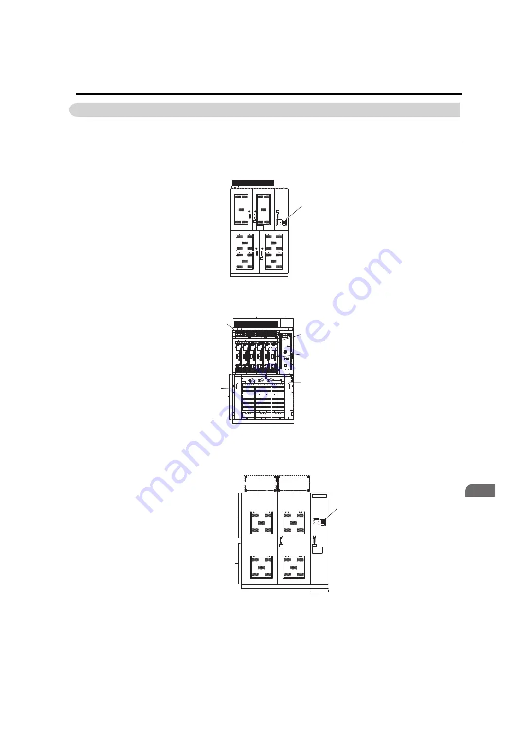
1.4 Component Names and Configurations
This section gives an overview of the drive components described in this manual.
u
External Appearance and Internal Layout
Drive external appearances and the layout of the internal devices are shown in
to
.
Figure 1.3
Figure 1.3 External Appearance, Viewing Doors (Drive: 2 kV class, 600 HP)
Figure 1.4
Figure 1.4 Internal Layout (Drive: 2 kV class, 600 HP)
Figure 1.5
Figure 1.5 External Appearance, Viewing Doors (Drive: 3 kV Class, 800 kVA)
A – Digital Operator
A – Cooling fans
D – Main circuit output terminals
B – Power Cells
E – Main circuit input terminals
C – Control circuit terminal
A – Digital Operator
A
Asia
E
A
B
C
D
Transformer panel
Power Cell panel
Control panel
%$
%$
%$
%$
%$
%$
%$
%$
ᵈᗧ
%#76+10
ᵈᗧ
%#76+10
ᵈᗧߊߛߐޕ
2NGCUGFQPQVECVEJVJGHKPIGT
DGVYGGPRCPGNHNCOGCPFVJKUWPKV
ޓࡄࡀ࡞ࡈ㧙ࡓߣᧄ࡙࠾࠶࠻ߣߩ㑆ߢᜰࠍ߹ߥࠃ߁ߦ
ޓャㅍᤨߩࡂࡦ࠼࡞ᛮߌ㒐ᱛ↪ߦࡄࡀ࡞ࡈ㧙ࡓⓣߣࡂࡦ࠼࡞
ߩ㑆ߦ⚿᧤ࡃࡦ࠼╬ࠍᏎ߈ઃߌߡਅߐޕ
2NGCUGFQPQVECVEJVJGHKPIGT
DGVYGGPRCPGNHNCOGCPFVJKUWPKV
㧭㧝
㧭㧞
㧮㧝
㧮㧞
㧯㧝
㧯㧞
'&'&
$0.
$0.
$0.
$0.
5%5%
4%4%
'&'&
'&'&
'&'&
'&'&
'&'&
'&'&
'&'&
'&'&
'&'&
'&'&
..
..
..
..
..
..
..
..
..
$0.
$0.
Asia
Transformer panel
Power Cell panel
Control panel
A
Asia
Summary of Contents for CIMR-MV2 Series
Page 8: ...8 YASKAWA ELECTRIC TOEP C710687 02B FSDrive MV1000 Instructions ...
Page 106: ...3 9 Wiring Check 106 YASKAWA ELECTRIC TOEP C710687 02B FSDrive MV1000 Instructions ...
Page 210: ...6 7 Spare Parts 210 YASKAWA ELECTRIC TOEP C710687 02B FSDrive MV1000 Instructions ...
Page 222: ...B 1 European Standards 222 YASKAWA ELECTRIC TOEP C710687 02B FSDrive MV1000 Instructions ...


