


21
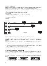
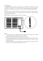
2.3.6 Set the delay switches
As described in section footprints and black spots, differences in the delays of the signals picked up by the
receiver from two or more radiators can cause black spots as a result of the multi path effect.
To compensate the signal delay differences, the delay of each radiator can be increased. These signal
delays can be set with the delay switches at the back of the radiator.
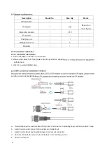
The cable signal delays can be determined in the following ways:
Calculate formula:
A: The farthest radiator cable length (from transmitter to the last radiator)
B: The radiator cable length (from transmitter to the radiator which need to set up)
C: The number of delay switch
C= (A-B)/10
For example:
The farthest radiator cable length (from transmitter to the last radiator) is 100 maters.
Cable length of radiator 1 is 50 meters, calculate formula is (100-50)/10=5, the delay switch number is 5
Cable length of radiator 2 and 5 is 100 meters, calculate formula is (100-100)/10=0, the delay switch
number is 0
Cable length of radiator 3 is 80 meters, calculate formula is (100-80)/10=2, the delay switch number is 2
Cable length of radiator 4 is 20 meters, calculate formula is (100-20)/10=8, the delay switch number is 8
Ø
s, used to connect the radiatos
r , please use the farthest radiator
cable length (from transmitter to the last radiator) as the base.
Ø
The radiator cable length in this system should be 10 meters integer times
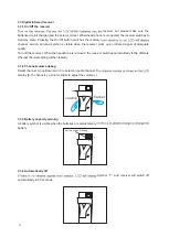
2.3.7 Determine the radiator delay switch positions
There are 8 dial radiator delay switch for set up, each dial sw
itch represents (1-8), please set the dial
switch according to the calculate formula, you also can set th n
eumber with the sum of 2 or more dial
switch numbers.
radiator 4, you can set the dial switch as
following:
set up with 1 dial switch
set up with 2 dial switch
set up with 3 dial switch
H
F o
u
t
1
2
3
4
50 Metes
50 Metes
80 Metes
20 Metes
1
100 Metes
2
3
5
4
On
Off
1
2
3
4
5
6
7
8
On
Off
1
2
3
4
5
6
7
8
On
Off
1
2
3
4
5
6
7
8


