background image

 14

SECTION 11:  ADJUSTMENTS

WARNING: 

Always stop the engine

and disconnect the spark plug wire
before performing any adjustments.

Figure 6  

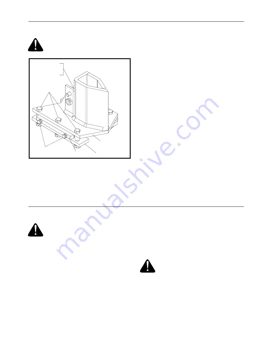
WEDGE PLATE ADJUSTMENT

As normal wear occurs, periodically adjust the bolts
on the side of the wedge plate as follows to
eliminate the excess space between the wedge
plate and the beam. See Figure 6.

Adjust wedge plate as follows:

1.

Loosen the three hex bolts on top of the wedge
plate (beneath the splitting wedge).

2.

Loosen the jam nuts on the two adjustment
bolts on the side of the gib plate, located
beneath the splitting wedge. Turn the
adjustment bolts in until snug, then back them
off slowly until the wedge assembly will slide on
the beam.

3.

Tighten the jam nuts securely against the gib
plate to hold the adjustment bolts in this position.

4.

Retighten the three hex bolts on top of the
wedge plate

GIB PLATE ADJUSTMENT

Periodically remove and replace the “gibs” (spacers)
between the wedge plate and the back plate as
follows.  See Figure 6.

NOTE: 

If desired, the gibs may be rotated and/or

turned over for even wear.

1.

Remove the center bolt on top of the wedge
plate. Slide the gib plate out.

2.

Remove and replace the gibs. Reassemble the
gib plate, making certain flat washers are in
place under the gib plate.

3.

Readjust the bolts on the side of the wedge
plate as instructed above.

SECTION 12:  MAINTENANCE

WARNING: 

Always stop the engine

and disconnect the spark plug wire
before performing any maintenance or
repairs.

RESERVOIR FLUID

Check the hydraulic fluid level in the log splitter
reservoir tank before each use. Fluid level should
be 1-1/2" to 2" from the top of the tank.
Change the hydraulic fluid in the reservoir every 100
hours of operation. Disconnect the suction hose
from the bottom of the reservoir tank, and drain the
fluid into a suitable container. Refill using only
Dexron III automatic transmission fluid or 10W non-
foaming hydraulic fluid.

NOTE: 

Drain the fluid and flush the reservoir tank

and hoses with kerosene whenever any repair work
is performed on the tank, hydraulic pump or valve.
Contaminants in the fluid will damage the hydraulic
components. (Should be performed by an
authorized service dealer.)

WARNING: 

Use extreme caution

when working with kerosene, as it is an
extremely flammable fluid.

HYDRAULIC FILTER

Change the hydraulic filter every 50 hours of
operation. Use only a 10 micron hydraulic filter.
Order part number 723-0405.

Attached
To Cylinder

Gib Plate

Back Plate

Hex Bolts

Adjustment Bolts

Wedge Plate

Summary of Contents for 550

Page 1: ...spark arrester meeting applicable local or state laws if any If a spark arrester is used it should be maintained in effective working order by the operator In the State of California the above is requ...

Page 2: ...our work zone Flying wood can be hazardous If a helper is assisting in loading logs never activate the control until the helper is clear of the area More accidents occur when more than one person oper...

Page 3: ...your work area clean Immediately remove split wood around your splitter so that you do not stumble over it Clean chips and dirt off end plate wood platform after each log is split or whenever necessar...

Page 4: ...eral times Do not remove the cap from the hydraulic tank or reservoir while your log splitter is running Hot oil under pressure could cause injury The pressure relief valve on your splitter is preset...

Page 5: ...e pump when mounting Operate through relief valve for more than several seconds Attempt to adjust unloading or relief valve settings without pressure gauges Operate with air in hydraulic system Use Te...

Page 6: ...se only Dexron III automatic transmission fluid or 10W non foaming hydraulic fluid 5 The flexible pump coupler must be inspected regularly Allowing the coupler to deteriorate will void your warranty D...

Page 7: ...nt should be used or sufficient people to prevent injury 1 Pry the top sides and ends off crate using a crowbar or large screwdriver 2 Set panels aside to avoid tire punctures or personal injury 3 Rem...

Page 8: ...pin E and clevis pin D Pivot the jack stand to the operating position and secure with the clevis pin D and spring pin E ASSEMBLY C See Figure 2 Attach the hitch as follows 1 Using two 9 16 wrenches r...

Page 9: ...ll the wheels 4 Place one wheel on each axle valve stem facing outward 5 Place one flat washer C just removed on each axle Secure with hex slotted nut B Tighten slotted nut until snug then back off ap...

Page 10: ...pump 2 This step will require two people Stand the wedge beam and cylinder assembly upright with cylinder to the top WARNING Use extreme caution as assembly is very heavy 3 Remove cotter pin M and cle...

Page 11: ...efill tank to within 1 1 2 to 2 from the top of the tank 10 Extend and retract the wedge fully 10 to 12 complete cycles to remove trapped air in the system system is self bleeding 11 Refill the reserv...

Page 12: ...ntal or vertical position and lock in place with the appropriate locking rod 3 Place a chock block in front and back of both wheels 4 Set the engine throttle at maximum speed 5 Place the log against t...

Page 13: ...position release rod out and pivot it down to release the beam Pivot the beam to the horizontal position Lock the beam in the horizontal position by pulling out on the horizontal beam lock and pivotin...

Page 14: ...e and replace the gibs Reassemble the gib plate making certain flat washers are in place under the gib plate 3 Readjust the bolts on the side of the wedge plate as instructed above SECTION 12 MAINTENA...

Page 15: ...mp coupler proceed as follows Follow the instructions carefully as the alignment is critical 1 Disconnect the spark plug wire and secure it away from the spark plug 2 Drain gasoline from fuel tank or...

Page 16: ...fuel shut off valve Fill tank with clean fresh gasoline Fuel will not last over thirty days unless a fuel stabilizer is used Move switch to ON position Clean fuel line Connect wire to spark plug Clea...

Page 17: ...ed repair Engine runs but wood will not split or wood splits too slowly Small gear section damaged Pump check valve leaking Excessive pump inlet vacuum Incorrect oil level Contaminated oil Directional...

Page 18: ...18 SECTION 16 ILLUSTRATED PARTS LIST...

Page 19: ...Push Cap 47 727 0311 Hitch Coupler 49 736 0116 Fl Wash 635 I D x 93 O D 50 736 0169 L Wash 3 8 I D 51 736 0185 Fl Wash 406 I D x 75 O D 52 750 0497 Spacer 3 8 I D x 625 O D 53 781 0162 Jack Stand 54 7...

Page 20: ...Department of MTD PRODUCTS INC Transportation charges Transportation charges for the movement of any power equipment unit or attachment are the responsibility of the purchaser Units exported out of th...

Reviews: