


ENGINE
6-42
TNV DI Service Manual
2-Valve Cylinder Head
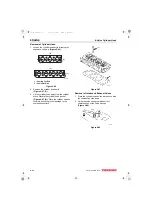
Use a telescoping gauge and micrometer to
measure the inside diameter at each end of the
valve guide. Measure in three places and 90° apart
(Figure 6-18). See Intake / Exhaust Valve and
Guide on page 6-7 for the service limit. Replace
valve guides if not within specification.
Figure 6-18
Inspection of Cylinder Head
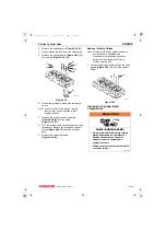
Cylinder Head Distortion
Place the cylinder head flat and inverted
(combustion side up) on the bench. Use a straight
edge and a feeler gauge to measure cylinder head
distortion (Figure 6-19). Measure diagonally and
along each side. See Cylinder Head on page 6-6
for the service limit.
Figure 6-19
If distortion exceeds the service limit, resurface or
replace the cylinder head. Remove only enough
material to make the cylinder head flat, but do not
remove more than 0.008 in. (0.20 mm).
Inspection of Intake and Exhaust Valves
Visually inspect the intake and exhaust valves.
Replace any valves that are obviously discolored,
heavily pitted or otherwise damaged.
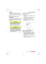
Valve Stem Diameter
Use a micrometer to measure the valve stem
diameter. Measure the valve stem near the
combustion end and near the opposite end
(Figure 6-20, (1)). See Intake / Exhaust Valve and
Guide on page 6-7 for the service limit.
Figure 6-20
Valve Stem Bend
Place the valve stem on a flat inspection block or
layout bed. Roll the valve until a gap can be
observed between a portion of the valve stem and
the surface of the block or bed. Use a feeler gauge
to measure the gap (Figure 6-21). See
Intake / Exhaust Valve and Guide on page 6-7 for
the service limit.
Figure 6-21
Valve Recession
Note: The valve guides must be installed to
perform this check.
Insert the valves into their original locations and
press them down until they are fully seated. Use a
depth micrometer (Figure 6-22) to measure the
difference between the cylinder head gasket
surface and the combustion surface of each
exhaust and intake valve (Figure 6-23). See
Cylinder Head on page 6-6 for the service limit.
0001869
0000192
0000197
(1)
0000199
TNV_DI_SM_A4.book 42 ページ 2007年12月6日 木曜日 午前9時23分