5. Inspection and Servicing of Basic Engine Parts
120
5.8 Flywheel and Housing
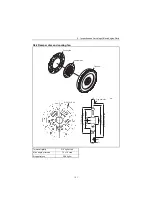
The function of the flywheel is through inertia, to rotate the crankshaft in a uniform and smooth manner
by absorbing the turning force created during the combustion stroke of the engine, and by compensating
for the decrease in turning force during the other strokes.
The flywheel is mounted and secured by 6 bolts on the crankshaft end at the opposite end to the gear
case; it is covered by the mounting flange (flywheel housing) which is bolted to the cylinder block.
the fitting surface for the damper disc is on the crankshaft side of the flywheel. The rotation of the
crankshaft is transmitted through this disc to the input shaft of the reduction and reversing gear. The
reduction and reversing gear is fitted to the mounting flange.
The flywheel’s unbalanced force on the shaft center must be kept below the specified value for the
crankshaft as the flywheel rotates with the crankshaft at high speed.
To achieve this, the valance is adjusted by drilling holes in the side of the flywheel, and the unbalanced
momentum is adjusted by drilling holes in the circumference.
The ring gear is shrink fitted onto the circumference of the flywheel, and this ring gear serves to start the
engine by meshing with the starter motor pinion.
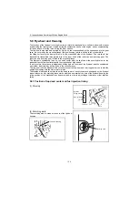
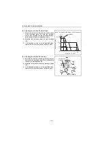
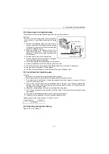
The stamped letter and line which show top dead center of each cylinder are positioned on the flywheel
circumference, and by matching these marks with the arrow mark at the hole of the flywheel housing, the
rotary position of the crankshaft can be ascertained in order to adjust tappet clearance or fuel injection
timing.
5.8.1 Position of top dead center and fuel injection timing
(1) Marking
(2) Matching mark
The matching mark is made at the hole of the flywheel
housing.
Hole
Flywheel
housing
Injection
timing marks
Flywheel
T.D.C.
No.1 cylinder
1
Matching mark
1
Hole
Flywheel housing


