


– 18 –
III-4 GEAR CASE
A. Disassembly
1. Using wrench, tail cap - special tool 102-801-3030 - loosen tail cap (G-31).
CAUTION
: LEFT HAND THREAD.
2. Remove tail cap and propeller shaft assembly by :
a. Removing O-ring (G-39)
b. Removing clip (G-38)
c. Removing guard plate (G-37)
d. Removing oil seal (G-35)
e. Removing spacer (G-36)
f. Removing clip (G-21)
g. Using special tool, Bevel Puller - Part # 102-809-0020 - remove gear (G-23)
h. Remove thrust washer (G-25)
i. Remove gear key (G-24)
j. Slowly heat tail cap assembly 100 ~ 120
O
C (200 ~ 250
O
F)
k. Tap propeller shaft gently from gear end to remove propeller shaft with
attached parts.
See figure16
.
1. Remove needle roller bearing (G-32).
m. Remove clip (G-21).
n. Remove two ball bearings (G-20).
3. Remove pinion gear nut (G-17) using 14 mm box wrench.
4. Remove clip (G-14).
5. Clamp pinion shaft (G-10) in vice.
6. Tap gear case with plastic or rubber hammer to remove pinion shaft with parts
attached.
7. Remove clip (G-12).
8. Remove ball bearing (G-11) by pressing.
9. Press needle roller bearing (G-2) down.
10. Clean all parts in solvent and dry with compressed air.
11. CAUTION: Do not spin bearing with compressed air.
Figure 16
Summary of Contents for 302
Page 1: ...302 YAMATO MOTOR CO LTD Ota Japan November 2012 M O D E L M A N U A L ...
Page 2: ...YAMATO EUROpE www YamatoRacing co uk ...
Page 14: ... 11 pOWER UNIT GROUp ...
Page 15: ...pOWER UNIT GROUp 12 ...
Page 18: ... 15 MAGNETO GROUp ...
Page 19: ... 16 CARBURETTOR GROUp ...
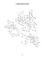
Page 23: ... 20 LOWER UNIT GROUp ...
Page 24: ... 21 LOWER UNIT GROUp ...
Page 25: ...GEAR CASE GROUp 22 ...
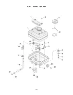
Page 26: ... 23 FUEL TANK GROUp ...
Page 27: ... 24 IV TROUBLESHOOTING ...
Page 28: ... 25 V CROSS SECTION OF MOTOR ...