FUEL TANK
6-1
EAM20140
FUEL TANK
EAM30263
REMOVING THE FUEL TANK
1. Extract the fuel in the fuel tank through the
fuel tank cap with a pump.
2. Remove:
•
Fuel hose coupler
WARNING
EWA19370
Cover the fuel hose connection with a cloth
when disconnecting it. This is because re-
sidual pressure in the fuel hose could cause
fuel to spurt out when the hose is removed.
NOTICE
ECA26520
• Make sure that the fuel hose is disconnect-
ed by hand. Do not forcefully disconnect
the hose with tools.
• When removing the fuel tank, handle it
carefully. If the discharge port of the fuel
pump touches the ground or other objects,
the discharge port could be damaged.
TIP
•
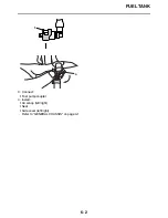
To disconnect the fuel hose from the fuel tank,
remove the fuel hose connector holder “a”, and
then slide the fuel hose connector cover.
•
To remove the fuel hose from the fuel rail, slide
the fuel hose connector cover “1” on the end of
the hose in the direction of the arrow shown,
press the two buttons “2” on the sides of the
connector, and then remove the hose.
•
Before removing the hose, place a few cloths
in the area under where it will be removed.
•
To prevent sand, dust, and other foreign mate-
rials from entering the fuel pump, install the in-
cluded fuel hose joint cover 1 “3” and the fuel
hose joint cover 2 “4” onto the disconnected
fuel hose and the fuel pump.
3. Remove:
•
Side cover (left/right)
•
Seat
•
Air scoop (left/right)
•
Fuel tank
TIP
Do not set the fuel tank down on the installation
surface of the fuel pump. Be sure to lean the fuel
tank against a wall or the like.
EAM30267
INSTALLING THE FUEL TANK
1. Install:
•
Fuel tank
2. Connect:
•
Fuel hose
NOTICE
ECA24740
• Connect the fuel hose securely, and check
that the orientation of the installed fuel
hose holder is correct.
• Take care not to kink or pinch the fuel hose.
TIP
•
Insert the fuel hose into the fuel pipe securely
until you hear a “click”.
•
Slide the fuel hose connector cover “1” at the
hose end in the direction of the arrow.
•
Install the fuel hose connector holder “a”.
•
Check that the fuel hose and the fuel pump
lead are routed through the guide on the cover.
a
1
2
3
4
Summary of Contents for YZ250FX 2021
Page 6: ...EAM20162 YAMAHA MOTOR CORPORATION U S A YZ MOTORCYCLE LIMITED WARRANTY ...
Page 8: ......
Page 10: ...MOTORCYCLE CARE AND STORAGE 1 18 CARE 1 18 STORAGE 1 19 ...
Page 46: ...TIGHTENING TORQUES 2 15 ...
Page 80: ...ELECTRICAL SYSTEM 3 32 ...
Page 96: ...HANDLEBAR 4 14 Throttle grip free play 3 0 6 0 mm 0 12 0 24 in ...
Page 107: ...FRONT FORK 4 25 1 ...
Page 116: ...CHAIN DRIVE 4 34 ...
Page 128: ...FUEL TANK 6 3 ...
Page 148: ...SELF DIAGNOSTIC FUNCTION AND DIAGNOSTIC CODE TABLE 8 13 ...
Page 158: ...CHASSIS 9 9 ...
Page 160: ......
Page 163: ...YZ250FXM 2021 WIRING DIAGRAM BAJ 2819U 11_WD indd 1 2020 06 29 15 46 05 ...
Page 164: ...YZ250FXM 2021 WIRING DIAGRAM BAJ 2819U 11_WD indd 2 2020 06 29 15 46 06 ...


