


A
B
C
D
E
F
G
H
1
2
3
4
5
6
I
J
K
L
7
8
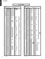
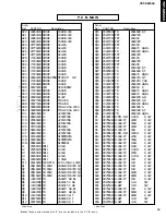
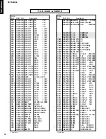
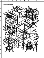
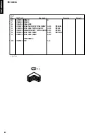
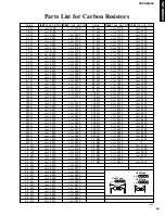
YST-SW800
■
SCHEMATIC DIAGRAM
* All voltage are measured with a 10M
Ω
/V DC electric volt meter.
* Components having special characteristics are marked
Z
and
must be replaced with parts having specifications equal to those
originally installed.
* Schematic diagram is subject to change without notice.
1SS133
1SR139-400
Anode
Cathode
B
C
E
2SC2240 (GR, BL)
2SD400 (F)
RBV-606
2SC4140
PIN CONNECTION DIAGRAM OF TRANSISTORS, DIODES AND ICS.
+
–
B
CE
2SC4163
S1NB20
+
–
1
2 3
1:OUTPUT
2:COMMON
3:INPUT
NJM78L08A
B
C
E
-1.3
-1.3
-1.4
-1.4
-1.4
-1.3
-1.5
-1.5
-1.3
8.8
-1.3
0.1
8.8
8.8
0.4
9.3
9.3
0.4
9.4
9.4
10.2
10.2
9.3
-18.1
10.2
-0.5
-0.5
-0.5
-1.5
0.4
-0.6
-0.5
-0.5
-0.5
5.9
6.0
0
12.1
11.9
11.9
7.8
0
1.2
0
0.7
1.2
AC 12.8V
CIRCUIT CHANGES BY MARKET.
X : NOT USED
O : USED
TM1661S-L
Point C
(Pin 1 of CB201)
V : 50V/div
H : 10
µ
sec/div
DC range
1 : 1 probe
0V
Point D
(Pin 1 of CB202)
V : 10V/div
H : 10
µ
sec/div
DC range
1 : 1 probe
0V
T1
T2
G
T1
T2 G
15