background image

IMPORTANT NOTICE

This manual has been provided for the use of authorized YAMAHA
Retailers and their service personnel.
It has been assumed that basic service procedures inherent to the industry,
and more specifically YAMAHA Products, are already known and
understood by the users, and have therefore not been restated.

WARNING:

Failure to follow appropriate service and safety
procedures when servicing this product may result in
personal injury, destruction of expensive components,
and failure of the product to perform as specified.  For
these reasons, we advise all YAMAHA product owners
that any service required should be performed by an
authorized YAMAHA Retailer or the appointed service
representative.

IMPORTANT:

The presentation or sale of this manual to any individual
or firm does not constitute authorization, certification or
recognition of any applicable technical capabilities, or
establish a principle-agent relationship of any form.

The data provided is believed to be accurate and applicable to the unit(s)
indicated on the cover.  The research, engineering, and service departments
of YAMAHA are continually striving to improve YAMAHA products.
Modifications are, therefore, inevitable and specifications are subject to
change without notice or obligation to retrofit.  Should any discrepancy
appear to exist, please contact the distributor's Service Division.

WARNING:

Static discharges can destroy expensive components.
Discharge any static electricity your body may have
accumulated by grounding yourself to the ground buss in
the unit (heavy gauge black wires connect to this buss).

IMPORTANT:

Turn the unit OFF during disassembly and part
replacement.  Recheck all work before you apply power
to the unit.

CONTENTS

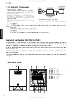
TO SERVICE PERSONNEL .......................................... 2
INTERNAL VIEW ........................................................... 
2
SPECIFICATIONS / 

参考仕様

........................................ 3

REAR PANELS .......................................................... 3~4
DISASSEMBLY PROCEDURES

 / 分解手順

............. 5~6

CONFIRMATION OF AUTO STANDBY OPERATION /

AUTO STANDBY 動作確認 ............................................

7

BLOCK DIAGRAM ......................................................... 8
PRINTED CIRCUIT BOARD .................................... 9~10
SCHEMATIC DIAGRAM .............................................. 11
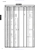
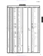
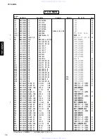
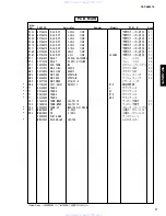
PARTS LIST ........................................................... 13~20

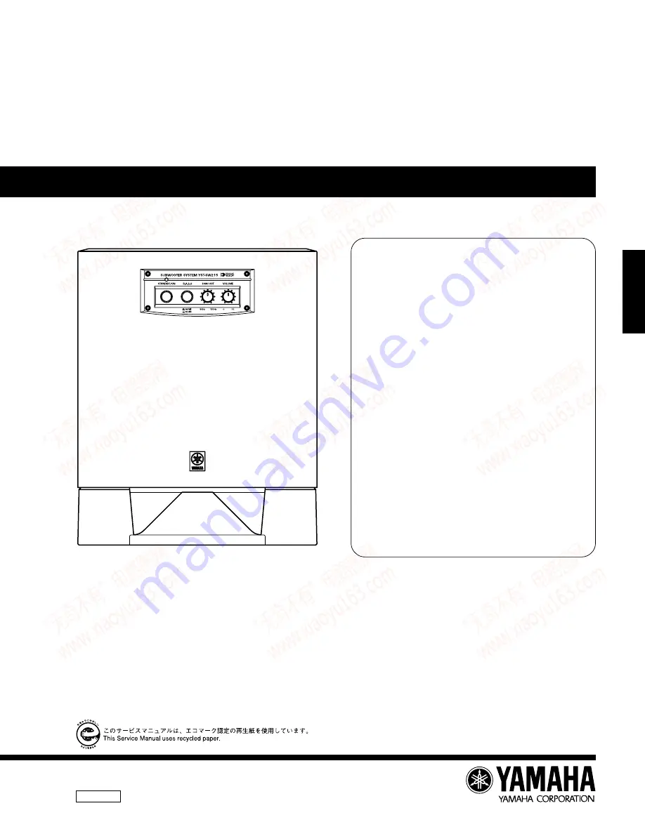
YST-SW215

1 0 0 8 5 4

P.O.Box 1, Hamamatsu, Japan

SERVICE  MANUAL

SUBWOOFER SYSTEM

YST-SW215

www. xiaoyu163. com

QQ 376315150

9

9

2

8

9

4

2

9

8

TEL 13942296513

9

9

2

8

9

4

2

9

8

0

5

1

5

1

3

6

7

3

Q

Q

TEL  13942296513  QQ  376315150  892498299 

TEL  13942296513  QQ  376315150  892498299 

http://www.xiaoyu163.com

http://www.xiaoyu163.com

Summary of Contents for YST-SW215

Page 1: ...he research engineering and service departments of YAMAHA are continually striving to improve YAMAHA products Modifications are therefore inevitable and specifications are subject to change without notice or obligation to retrofit Should any discrepancy appear to exist please contact the distributor s Service Division WARNING Static discharges can destroy expensive components Discharge any static ...

Page 2: ...ectrical electronic and or plastic where applicable components may also contain traces of chemicals found by the California Health and Welfare Agency and possibly other entities to cause cancer and or birth defects or other reproductive harm DO NOT PLACE SOLDER ELECTRICAL ELECTRONIC OR PLASTIC COMPONENTS IN YOUR MOUTH FOR ANY REA SON WHATSOEVER Avoid prolonged unprotected contact between solder an...

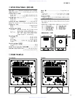
Page 3: ...del AC 100 V 50 60 Hz Power Consumption 消費電力 U C A B G R T K models 95 W J model 70 W Standby Power Consumption 待機時消費電力 0 5 W Dimensions 外形寸法 W x H x D 290 x 360 x 322 mm 11 7 16 x 14 3 16 x 12 11 16 Weight 質量 11 5 kg 25 lbs 6 oz Finish Cherry Color U C A B G R T K J models Black Color U C A B G R T J models Accessories 付属品 Subwoofer Cable 3 m x 1 J model Speaker cable 4 m x 2 J model Nonskid Pad ...

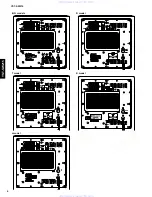
Page 4: ...del K model R model www xiaoyu163 com QQ376315150 9 9 2 8 9 4 2 9 8 TEL 13942296513 9 9 2 8 9 4 2 9 8 0 5 1 5 1 3 6 7 3 Q Q TEL 13942296513 QQ 376315150 892498299 TEL 13942296513 QQ 376315150 892498299 http www xiaoyu163 com http www xiaoyu163 com ...

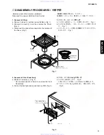
Page 5: ...connected to the terminal of the Driver Fig 1 Fig 2 Fig 1 2 フロントパネルAss yの外し方 a のネジ4本を外します Fig 2 取り外しには六角レンチ 2 5mm を使用します b フロントパネルAss yを引き出し CB4を外します Fig 2 2 Removal of Front Panel Ass y a Remove 4 screws 3 Fig 2 Use an Allen wrench 2 5mm to unscrew the Front Panel Ass y b Pull out the front panel ass y and remove CB4 Fig 2 Speaker Unit スピーカーユニット 2 2 Base ベース 1 1 Connector コネクター CB4 Front panel As...

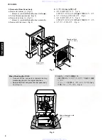
Page 6: ...r cover Fig 3 When Checking the P C B Connect all the connectors removed during disassembly back to the original positions Spread cloth first and place the rear panel ass y on it Fig 4 P C B チェックをする場合には 分解の際に外したコネクターをすべて元通りに接続 します ゴムシートと布を敷き その上にリアパネルAss y を置いてチェックします Fig 4 Fig 4 4 5 5 4 Rear panel Ass y リヤパネル Ass y Rear Cover リヤカバー Rubber sheet and cloth ゴムシートと布 www xiaoyu163 com QQ376315150 9 9 ...

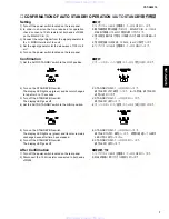
Page 7: ... signal generator for the sine wave of 100 Hz 8 mV 5 Turn on the power switch located on the rear panel Confirmation 1 Set the AUTO STANDBY switch to the LOW position 2 Turn on the STANDBY ON switch The display LED lights up green and its color changes to red after 5 to 10 seconds 3 Turn off the STANDBY ON switch The display LED goes off 4 Set the AUTO STANDBY switch to the HIGH position 5 Turn on...

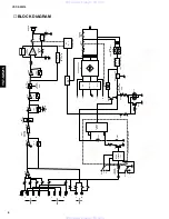
Page 8: ...4 REGULATOR R T K models only POWER SW5 A N I C IC2 Q16 L P F 6dB oct 1 12 Q21 22 D24 IC11A IC11B IC7A VR1 VOLUME L P F 6dB oct B P F Q201 204 L P F 12dB oct 3 6 1 5 8 IC7B 4 2 2 HIGH CUT VR2 L R INPUT 1 L R INPUT 2 L R OUTPUT IC10A 7 8 7 6 SW1 PHASE SELECT IC10B L P F 12dB oct 4 2 BASS SELECT SW3 H P F 12dB oct 6 LIMITER H OFF L www xiaoyu163 com QQ376315150 9 9 2 8 9 4 2 9 8 TEL 13942296513 9 9 ...

Page 9: ... BOARD Foil side Ref No Location D1 J3 D2 I4 D3 J4 D4 F3 D5 F3 D6 H3 D7 F3 D9 H4 D12 I6 D19 H3 D20 G3 D21 G3 D22 F4 D23 F4 D24 J3 D202 H6 IC1 H2 IC2 H4 IC3 H4 IC4 D5 IC7 F6 IC10 C3 IC11 D5 IC201 D4 Q1 G3 Q2 G3 Q5 F4 Q6 F4 Q7 F3 Q8 G3 Q9 I4 Q10 J4 Q16 G4 Q21 H4 Q22 H4 Q201 D2 Q202 D3 Q203 D2 Q204 D2 Q205 C4 Q206 H6 Semiconductor Location w w w x i a o y u 1 6 3 c o m Q Q 3 7 6 3 1 5 1 5 0 9 9 2 8 9...

Page 10: ...WH RE RE BL BL YE YE BR BR GR GR BE BE OR GY GY MAIN 1 P C B RE RE BL PRINTED CIRCUIT BOARD Foil side Semiconductor Location Ref No Location D203 B3 D204 A3 D205 B3 IC202 A2 Q207 A3 Q208 A3 Q209 A3 w w w x i a o y u 1 6 3 c o m Q Q 3 7 6 3 1 5 1 5 0 9 9 2 8 9 4 2 9 8 T E L 1 3 9 4 2 2 9 6 5 1 3 9 9 2 8 9 4 2 9 8 0 5 1 5 1 3 6 7 3 Q Q TEL 13942296513 QQ 376315150 892498299 TEL 13942296513 QQ 376315...

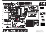
Page 11: ... are measured with a 10M V DC electric volt meter H Components having special characteristics are marked s and must be replaced with parts having specifications equal to those originally installed H Schematic diagram is subject to change without notice 1 12 0 0 0 1 4 0 0 0 1 0 7 0 0 1 14 6 14 8 1 9 0 0 0 0 0 0 0 0 0 0 0 1 5 6 6 8 0 8 0 4 6 4 6 5 4 0 4 9 14 6 0 0 0 0 0 0 0 0 0 1 0 1 0 1 3 9 6 8 6 7...

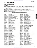
Page 12: ...ET FL DSPLY FLUORESCENT DISPLAY FLTR CE CERAMIC FILTER FLTR COMB COMB FILTER MODULE FLTR LC RF LC FILTER EMI GND MTL GROUND PLATE GND TERM GROUND TERMINAL HOLDER FUS FUSE HOLDER IC PRTCT IC PROTECTOR JUMPER CN JUMPER CONNECTOR JUMPER TST JUMPER TEST POINT L DTCT LIGHT DETECTING MODULE L EMIT LIGHT EMITTING MODULE LED DSPLY LED DISPLAY LED INFRD LED INFRARED MODUL RF MODULATOR RF PHOT CPL PHOTO COU...

Page 13: ...70 C EL 47uF 16V ケミコン 01 C22 UR867220 C EL 22uF 50V ケミコン 01 C23 UR865470 C EL 0 47uF 50V ケミコン 01 C24 UR828220 C EL 220uF 10V ケミコン 01 C25 WB540200 C POL MTL 0 1uF ECQE2104KF3 メタライズドポリコン C26 WB540200 C POL MTL 0 1uF ECQE2104KF3 メタライズドポリコン C29 UR867220 C EL 22uF 50V ケミコン 01 C30 UR867220 C EL 22uF 50V ケミコン 01 C31 UR867220 C EL 22uF 50V ケミコン 01 C32 UR867220 C EL 22uF 50V ケミコン 01 C33 UA655100 C MYLAR 0 ...

Page 14: ...RTK ケミコン 01 C240 UR749100 C EL 1000uF 25V JUCABG ケミコン 01 C241 UR867100 C EL 10uF 50V ケミコン 01 s D1 VN011300 DIODE BRG D3SBA20 4A 200V ダイオード 03 D2 VG440900 DIODE ZENR MTZJ15C 15V ツェナーダイオード 01 D3 VG440900 DIODE ZENR MTZJ15C 15V ツェナーダイオード 01 D4 VD631600 DIODE 1SS133 176 ダイオード 01 D5 VD631600 DIODE 1SS133 176 ダイオード 01 D6 VD631600 DIODE 1SS133 176 ダイオード 01 D7 VG442500 DIODE ZENR MTZJ24B 24V ツェナーダイオード 01 ...

Page 15: ...TR 2SC2240 GR BL RTK トランジスタ 01 Q208 VK801200 TR 2SC4688 R O RTK トランジスタ 04 Q209 iC224030 TR 2SC2240 GR BL トランジスタ 01 R1 HV756390 R CAR FP 3 9KΩ 1 4W 不燃化カーボン抵抗 01 R5 HV756120 R CAR FP 1 2KΩ 1 4W 不燃化カーボン抵抗 01 R27 HB027100 R MTL FLM 10KΩ 1 4W 金属被膜抵抗 R28 V6022600 R WW 0 1Ω 3W セメント抵抗 R30 HV756100 R CAR FP 1KΩ 1 4W 不燃化カーボン抵抗 01 R31 HB027200 R MTL FLM 20KΩ 1 4W 金属被膜抵抗 R32 HV754820 R CAR FP 82Ω 1 4W 不燃化カーボン...

Page 16: ...2000 SW SLIDE SSSF12 スライドSW 02 SW2 VD179500 SW SLIDE SSSU12 スライドSW 04 SW3 VS066500 SW PUSH SPPH13 W プッシュスィッチ 03 SW4 VS066500 SW PUSH SPPH13 W プッシュスィッチ 03 SW5 V8377400 SW POWER SY16 52 4 パワースィッチ s SW6 V7182300 VOLT SELCT R8140213 RTK 電圧切替器 s T1 X4335A00 TRANS J サブトランス s T1 X4336A00 TRANS UC サブトランス s T1 X4337A00 TRANS RTK サブトランス s T1 X4338A00 TRANS ABG サブトランス TE1 VT658100 TERM WRAP 352 TX119 ラッピング端子...

Page 17: ...5 3470 HF85 3470 5 6 Ω HJ35 3560 HF85 3560 10 Ω HF45 4100 HF45 4100 15 Ω HJ35 4150 HF85 4150 22 Ω HF45 4220 HF45 4220 27 Ω HJ35 4270 HF85 4270 33 Ω HF45 4330 HF45 4330 39 Ω HJ35 4470 HF85 4390 47 Ω HF45 4470 HF45 4470 56 Ω HF45 4560 HF45 4560 68 Ω HF45 4680 HF45 4680 75 Ω HF45 4750 HF45 4750 82 Ω HF45 4820 HF45 4820 91 Ω HF45 4910 HF45 4910 100 Ω HF45 5100 HF45 5100 110 Ω HJ35 5110 HF85 5110 120 Ω...

Page 18: ...0 POWER CABLE 2m A 電源コード s 4 3 V6977100 POWER CABLE 2m B 電源コード s 4 3 V6893100 POWER CABLE 2m G 電源コード 4 4 CB072750 CORD STOPPER SR 4N 4 コードストッパー 01 4 5 CB069250 BINDING TIE BK 1 束線止め 01 4 11 WB277800 REAR PANEL J リアパネル 4 11 WB277900 REAR PANEL UC リアパネル 4 11 WB278000 REAR PANEL RTK リアパネル 4 11 WB278100 REAR PANEL A リアパネル 4 11 WB278200 REAR PANEL BG リアパネル 4 16 WA217100 POWER KNOB CH パワーノブ 01 4 18 WB25...

Page 19: ...1 V3262500 SUBWOOFER CABLE 1P 3m 1pc サブウーハーケーブル 04 202 WB365800 NON SKID PAD M32 t2 4pcs set 滑止パッド YST SW215 w w w x i a o y u 1 6 3 c o m Q Q 3 7 6 3 1 5 1 5 0 9 9 2 8 9 4 2 9 8 T E L 1 3 9 4 2 2 9 6 5 1 3 9 9 2 8 9 4 2 9 8 0 5 1 5 1 3 6 7 3 Q Q TEL 13942296513 QQ 376315150 892498299 TEL 13942296513 QQ 376315150 892498299 http www xiaoyu163 com http www xiaoyu163 com ...
Reviews: