A
1
2
3
4
5
6
7
8
9
10
B
C
D
E
F
G
H
I
J
K
L
M
N
YSP-1000
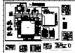
SCHEMATIC DIAGRAM (DSP 1/3)
61
★
All voltages are measured with a 10M
Ω
/V DC electronic volt meter.
★
Components having special characteristics are marked
s
and must be replaced
with parts having specifications equal to those originally installed.
★
Schematic diagram is subject to change without notice.
Voltage
regulator
Overcurrent
detection
circuit
Overheat
detection
circuit
ON/OFF
circuit
Q
R
S
F/F
2
5
4
1
3
COM
PWM COMP.
V
IN
V
OUT
ON/OFF
control
O
adj
V
ref
ERROR AMP.
Soft start
Oscillator
IC1~3
: PQ1CZ41H2Z
Chopper Regulators
Input
Selector
RXOUT
RX0
RX1
RX2
RX3
RX4
RX5/VI
RX6/UI
LPF
TMCK/PIO0
TBCK/PIO1
TLRCK/PIO2
TDATA/PIO3
TXO/PIOEN
Cbit, Ubit
Microcontroller
I/F
Data
Selector
Clock
Selector
Modulation
&
Parallel Port
PLL
XIN
XOUT XMCK CKST
SLRCK
SBCK
RLRCK
RBCK
RMCK
SDIN
RDATA
RERR
DO
XMODE
CI
CE
CL
INT
AUDIO/VO
EMPHA/UO
1/N
Demodulation
&
Lock detect
1
2
3
4
5
8
9
10
13
44
45
46
47
48
29
28
27
34
23
22
20
17
16
24
21
36
37
41
38
39
48
35
33
32
IC4
: LC89057W-VF4D-E
Digital Audio Interface Transceiver
Pin Multiple
EMIF32
L1P Cache
Direct Mapped
4K Bytes Total
Digital Signal Processors
L1D Cache
2-Way Set
Associative
4K Bytes Total
Clock Generator,
Oscillator and PLL
x4 through x25 Multipliers
/1 through /32 Dividers
Power-Down
Logic
Instruction Fetch
Instruction Dispatch
Instruction Decode
Data Path B
Data Path A
B Register File
Control
Registers
C67x
TM
CPU
Control
Logic
In-Circuit
Emulation
Interrupt
Control
Test
A Register File
.L1t
McASP1
McASP0
McBSP1
McBSP0
I2C1
I2C0
Timer 1
Timer 0
.S1t .M1t .D1
.D2 .M2t .S2t .L2t
GP1
GP0
HPI16
Enhanced
DMA
Controller
(16 channel)
L2 Cache/
Memory
4 Banks
64K Bytes
Total
(4-Way)
L2
Memory
DA610:
192K Bytes
DA601:
64K Bytes
R2 ROM
512K
Bytes
Total
IC5
: D60YA003BPYP225
Decoder
IC6
: SN74AHC1G08DCKR
2-Input And Gate
1
DIR
A1
A2
A3
A4
A5
A6
A7
A8
GND
Vcc
OE
B1
B2
B3
B4
B5
B6
B7
B8
2
3
4
5
6
7
8
9
10
20
19
18
17
16
15
14
13
12
11
IC8
: SN74LV245APWR
Octal Bus Transceivers with 3-state Outputs
1
2
3
4
5
6
7
14
13
12
11
10
9
8
1CLR
1D
1CLK
1PRE
1Q
1Q
GND
VCC
2CLR
2D
2CLK
2PRE
2Q
2Q
TG
C
C
TG
C
C
TG
C
C
C
TG
C
C
PRE
CLK
D
CLR
Q
Q
C
IC7
: SN74LVC74APWR
DUAL POSITIVE-EDGE-TRIGGERED D-TYPE FLIP-FLOPS
9
5
10
7
8
1
14
13
3
12
2
6
4
11
AVDD
CAP
AGND
RIN
LIN
DVDD
DGND
SDATO
LRCLK
BCLK
MCLK
VREF
FMT
NOHP
ADC
ADC
DIGITAL
FILTERS
AUDIO
INTERFACE
CONTROL
INTERFACE
IC10
: WM8738
24bit Stereo ADC
V
SS
V
CC
WE
CE
A
0
to A
17
OE
Erase Voltage
Generator
DQ
0
to DQ
15
State
Control
Command
Register
Program Voltage
Generator
Low V
CC
Detector
Address
Latch
X-Decoder
Y-Decoder
Cell Matrix
Y-Gating
Chip Enable
Output Enable
Logic
Data Latch
Input/Output
Buffers
STB
STB
Timer for
Program/Erase
A
-1
BYTE
RESET
RY/BY
Buffer
RY/BY
IC11
: MBM29LV400BC-70PFT
FLASH MEMORY
IC9
: W9816G6CH-7
512K x 2 Banks x 16 Bits SDRAM
CLOCK
BUFFER
ADDRESS
BUFFER
CLK 35
18
CKE 34
A10 20
CS
17
RAS
16
CAS
15
WE
21
A0
24
A3
27
A4
32
A9
19
BA
2
DQ0
3
DQ1
5
DQ2
6
DQ3
8
DQ4
9
DQ5
11 DQ6
12 DQ7
39 DQ8
40 DQ9
42 DQ10
43 DQ11
45 DQ12
46 DQ13
48 DQ14
49 DQ15
14 LDQM
36 UDQM
COMMAND
DECODER
REFRESH
COUNTER
REFRESH
COUNTER
DQ
BUFFER
COLUMN
COUNTER
MODE
REGISTER
CONTROL
SIGNAL
GENERATOR
CELL ARRAY
BANK #0
R
O
W
D
E
C
O
D
E
R
COLUMN DECODER
SENSE AMPLIFIER
CELL ARRAY
BANK #1
R
O
W
D
E
C
O
D
E
R
COLUMN DECODER
SENSE AMPLIFIER
POINT
B-1 Pin 13 of IC26
10.4
3.4
0
1.3
6.8
3.3
0
10.4
1.3
0
1.3
6.8
1.3
0
10.4
2.7
0
1.3
6.7
2.7
0
0.4
3.3
0
0
0
0
3.3
1.5
1.6
1.6
3.3
0
0
5,1
0
3.3
0
3.3
0
3.3
0
1.7
1.7
0
3.3
1.7
0
0
3.3
0
3.2
3.3
0.1
~
3.1
3.3
3.3
3.3
0
3.3
3.3
3.3
1.7
1.6
3.3
1.7
1.7
0
0
3.3
3.3
~
2.5
3.3
0
3.3
0
3.1
3.1
0.7
0.7
4.1
3.3
1.3
1.7
0
2.6
2.6
2.6
0
1.7
1.7
0
0
5.0
2.5
5.0
2.5
5.0
2.6
2.5
0
2.6
0
3.3
3.1
3.1
0
3.1
3.1
3.3
3.1
3.1
0
3.1
3.1
3.3
3.2
3.3
3.3
3.3
3.3
1.0
0
0.1
0.2
3.1
3.1
3.3
0
0
0
0
1.0
0
0
0
3.3
3.2
0
0
1.0
1.1
1.5
1.9
3.1
3.1
0.2
0
3.3
0
3.1
3.1
3.1
3.1
3.1
3.1
3.1
3.1
3.3
3.1
3.1
3.1
3.1
3.1
3.1
3.1
3.1
3.3
0
3.3
0.1
0
3.1
3.1
0
3.1
3.1
3.3
3.1
3.1
0
3.1
3.1
3.3
3.2
1.7
0
0
1.0
1.1
1.5
1.9
0.1
1.3
0
3.3
3.3
3.3
0
1.3
0
1.3
0
0
0
1.7
1.3
0
1.7
3.3
0
1.3
0
3.2
3.1
3.3
0
1.3
~
0
1.3
3.3
3.3
1.3
3.3
0
1.3
3.3
0
0
1.3
1.3
0
3.3
1.7
0.1
1.7
1.3
3.3
1.3
1.3
0
3.3
0.7
1.3
0
0
0
3.3
1.7
1.7
3.3
3.3
0
3.1
3.1
3.1
3.1
3.1
3.1
3.2
0
1.3
3.1
3.1
3.1
3.1
3.1
3.1
3.1
1.3
0
3.3
3.1
3.1
3.1
3.2
3.2
3.3
0
1.3
1.3
0
3.3
3.3
3.3
0
1.3
0.1
0.2
3.1
3.3
0
1.3
3.1
1.9
1.5
1.1
3.3
0
1.0
3.3
1.7
0
3.3
1.3
0
3.3
3.3
0
0
3.3
0
1.3
0
1.0
0
0
0
0
1.3
0
3.3
0
0
0
3.3
3.3
1.3
1.3
0
3.3
1.6
3.3
0
3.3
1.3
0
0
1.3
1.3
0
3.3
3.3
3.3
1.3
0
3.3
3.3
3.3
3.3
0
3.3
0
1.3
3.3
3.3
0
0
3.3
1.3
0
1.3
3.3
3.3
3.3
0
1.7
0
1.3
0
0
3.2
3.3
0
DSP
XTAL
F.F
ADC
DRAM
FLASH
Page 62
to DSP_CB4
D3
Y
4
B
2
GND
3
Vcc
5
A
1
Summary of Contents for YSP 1000 - Digital Sound Projector Five CH...
Page 60: ...YSP 1000 60 MEMO MEMO...


