5 - 5
COOL
EBS00129
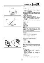
THERMOSTAT
LS
5
6
2
3
4
1
T
R
.
.
10 Nm (1.0 m
•
kg, 7.2 ft
•
Ib)
T
R
.
.
18 Nm (1.8 m
•
kg, 13 ft
•
Ib)
New
New
New
Order
Job/Part
Q’ty
Remarks
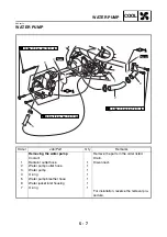
Removing the thermostat
Remove the parts in the order listed.
Front fender
Refer to “SEAT, FENDERS AND FUEL
TANK” in chapter 3.
Coolant
Drain.
1
Radiator inlet hose
1
2
Thermostat cover
1
3
O-ring
1
4
Thermostat
1
5
Coolant temperature sensor
1
6
Copper washer
1
For installation, reverse the removal pro-
cedure.
Summary of Contents for YFM700RV 2006
Page 1: ...YFM700RV SERVICE MANUAL 1S3 28197 E0 ...
Page 34: ...2 11 SPEC ENGINE SPECIFICATIONS Cylinder head tightening sequence 1 3 2 4 5 7 8 6 ...
Page 52: ...2 29 SPEC OIL FLOW DIAGRAMS 1 Oil delivery pipe 2 Oil filter 3 Oil pump 2 3 A A A A 2 1 ...
Page 55: ...2 32 SPEC OIL FLOW DIAGRAMS 1 Balancer 1 2 Crankshaft 2 1 ...
Page 408: ...YAMAHA MOTOR CO LTD 2500 SHINGAI IWATA SHIZUOKA JAPAN ...


