


–9–
1
2
B
1
A
1
1
2
A
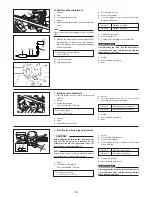
6. Handlebar bands
1
Band
4
4
- V
A: Clamp the handlebar switch lead
and the rear brake light switch
lead.
B: Clamp the front brake light switch
lead and on command four-wheel
drive switch lead.
NOTE:
Refer to “CABLE ROUTING”.
4. Rear brake cable and rear brake light switch
1
2
Rear brake cable
Rear brake light switch
1
1
2
-
*
2
-
*
5. Handlebar switch
1
2
2
-
*
2
- V
Handlebar switch
Panhead screw
1
2
A: Tighten the screws in stages and
maintain an equal gap on each
side of the handlebar switch.
WARNING
Proper cable routing is essential to
assure safe machine operation.
Refer to “CABLE ROUTING”.
d = 5 (0.20),
R
= 30 (1.17)