background image

Adjusting the virtual speaker settings

25

 En

AD

V

ANCED


OPERA

T

ION

Eng

lish

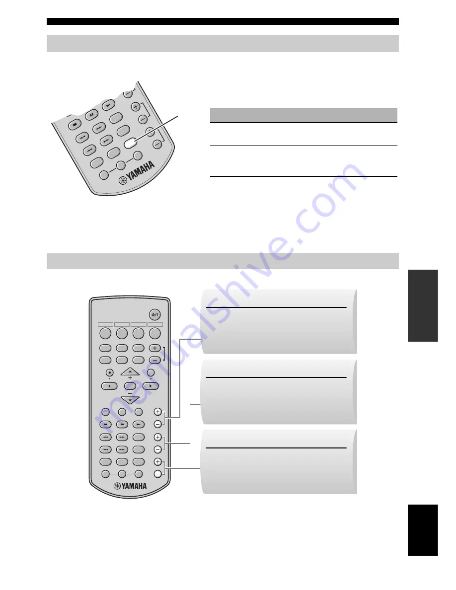
Use this feature to set the equalizer to optimize the tonal quality of the sound for the acoustic characteristics of your 
listening room.

You can also adjust the output level of the virtual center, virtual surround speakers, and subwoofer during playback. 

Adjusting the characteristics of the tonal quality (ROOM EQ)

Adjusting the speaker balance during playback

DISP

. MODE

DIMMER

ROOM E

Q

DEC.

 MODE

CEN

TER

SW

NIGHT

MEMO

RY

A

AU

TO


/MAN'L

PRESET 

/TUNE

R

SUR.

L

TEST

Press 

ROOM EQ

 repeatedly to select the desired 

room equalizer setting.

Choice

Descriptions

HARD

If the walls in your listening room are hard and you can 
get the sufficiently reflected sounds

SOFT

If the walls are covered over some soft objects or there 
are some furniture on the walls and you cannot get the 
sufficiently reflected sounds

ROOM EQ

ENTER

DISP. MODE

DIMMER

ROOM EQ

DEC. MODE

CENTER

SW

NIGHT

MEMORY

AUTO 

   /MAN'L

PRESET 

/TUNE

R

SUR.

L

TEST

MUTE

A  E

A  E

MENU

DOCK

FM

INPUT

INPUT 3

INPUT 2

INPUT 1

MOVIE

MUSIC

SPORTS

GAME

STANDBY/ON

VOLUME

SW +/–

Adjusts the output level of the subwoofer 
channel.
Control range: +8 to –8

/–

Adjusts the output level of the virtual center 
speaker channel.
Control range: +4 to –4

SUR. +/–

Adjusts the output level of the virtual surround 
speaker channels.
Control range: +4 to –4

Summary of Contents for YAS-70BL

Page 1: ...YAS 70 YAS 70CU YAS 70SPX CENTER SYSTEM SUBWOOFER SYSTEM CONTROL OWNER S MANUAL U ...

Page 2: ...ctrician for replacement of the obsolete outlet 10 Protect the power cord from being walked on or pinched particularly at plugs convenience receptacles and the point where they exit from the apparatus 11 Only use attachments accessories specified by the manufacturer 12 Use only with the cart stand tripod bracket or table specified by the manufacturer or sold with the apparatus When a cart is used ...

Page 3: ...equencies and if not installed and used according to the instructions found in the users manual may cause interference harmful to the operation of other electronic devices Compliance with FCC regulations does not guarantee that interference will not occur in all installations If this product is found to be the source of interference which can be determined by turning the unit OFF and ON please try...

Page 4: ...d may cause fire damage to this unit and or personal injury Yamaha will not be held responsible for any damage resulting from use of this unit with a voltage other than specified 13 To prevent damage by lightning keep the power cord and outdoor antennas disconnected from a wall outlet or the unit during a lightning storm 14 Do not attempt to modify or fix this unit Contact qualified Yamaha service...

Page 5: ...isplay 21 Adjusting the virtual speaker settings 22 Using the speaker test mode 23 Adjusting the characteristics of the tonal quality ROOM EQ 25 Adjusting the speaker balance during playback 25 Additional information 26 Troubleshooting 26 Glossary 28 Specifications 29 Contents INTRODUCTION PREPARATION BASIC OPERATION ADVANCED OPERATION ADDITIONAL INFORMATION Introduction YAS 70 consists of the cen...

Page 6: ...X x 1 System control cable 4 m x 1 Spacer x 2 Remote control x 1 Speaker cable 4 m x 2 Battery x 2 AAA R03 UM4 Indoor FM antenna x 1 DISP MODE DIMMER ROOM EQ DEC MODE CENTER SW NIGHT MEMORY MUTE A E A E MENU DOCK FM INPUT INPUT 3 INPUT 2 INPUT 1 MOVIE MUSIC SPORTS GAME STANDBY ON VOLUME AUTO MAN L PRESET TUNE R SUR L TEST ENTER Mounting template x 1 Double sided tape Small 4 pieces x 1 Double side...

Page 7: ... the information about the operational status of this system P 4 Remote control sensor Receives infrared signals from the remote control P 5 Power indicator Lights up when this system is turned on P 13 VOLUME Controls the volume of this system P 13 INPUT Selects an input source you want to listen to P 13 STANDBY ON Turns on this system or sets it to the standby mode P 13 ...

Page 8: ...hen this system is receiving a strong signal from an FM stereo broadcast while the AUTO indicator is lit P 17 MEMORY indicator Flashes to show a station can be stored P 18 Multi information display Shows the selected input source When you are adjusting or changing setting the name of the current sound field program and other information is displayed Decoder indicators The respective indicator ligh...

Page 9: ... INPUT 3 INPUT 2 INPUT 1 STANDBY ON VOLUME Sound field program buttons Select a sound field program P 14 Input buttons Select an input source you want to listen to P 13 Control iPod and FM tuner P 16 and 20 Control iPod P 20 Adjust the brightness of the front panel display P 21 Turns on this system or sets it to the standby mode P 13 Control the volume of this system P 13 Turns on or off the night...

Page 10: ...t use different types of batteries for example alkaline and manganese together Each type of battery has its own characteristics even if they are similar in shape If the batteries run out immediately remove them from the remote control to prevent an explosion or acid leak Dispose of the batteries according to the regional regulations If a battery starts leaking dispose of it immediately Be careful ...

Page 11: ...e heard differently depending on the listening position and subwoofer location To enjoy desired sounds try changing the location of the subwoofer Depending on your installation environment connections with external components can be done before installing this system We recommend that you temporarily place and arrange all components in order to decide which procedure must come first You can place ...

Page 12: ... system fix the speaker cables in place so that cables do not loosen If your foot or hand accidentally gets caught on a loose speaker cable the center system may fall After attaching the center system check that the center system is fixed securely Yamaha will bear no responsibility for any accidents caused by improper installations When installing the center system on a wall all installation work ...

Page 13: ...g so may damage the cable plug and or terminal Connecting the center system and the subwoofer system control SYSTEM CONNECTOR DOCK INPUT L ANALOG FM 75Ω UNBAL OPTICAL COAXIAL 3 1 2 SPEAKERS ANTENNA L R R Speaker cables supplied Connect the cable plug to the speaker jack of the same color Connect the cable plug to the speaker jack of the same color SYSTEM CONNECTOR DOCK INPUT L ANALOG FM 75Ω UNBAL ...

Page 14: ...ling frequency is 96 kHz or less INPUT 1 OPTICAL jack Example 1 DVD player Example 2 TV game console INPUT 2 COAXIAL jack Connecting external components Notes SYSTEM CONNECTOR DOCK INPUT L ANALOG FM 75Ω UNBAL OPTICAL COAXIAL 3 1 2 SPEAKERS ANTENNA L R R DIGITAL OUT OPTICAL DVD player TV Optical digital cable SYSTEM CONNECTOR DOCK INPUT L ANALOG FM 75Ω UNBAL OPTICAL COAXIAL 3 1 2 SPEAKERS ANTENNA L...

Page 15: ...video camera VCR or video camera etc with no digital output SYSTEM CONNECTOR DOCK INPUT L ANALOG FM 75Ω UNBAL OPTICAL COAXIAL 3 1 2 SPEAKERS ANTENNA L R R L R AUDIO OUTPUT TV SYSTEM CONNECTOR DOCK INPUT L ANALOG FM 75Ω UNBAL OPTICAL COAXIAL 3 1 2 SPEAKERS ANTENNA L R R R L AUDIO OUTPUT Video camera VCR etc ...

Page 16: ... control Connecting a Yamaha iPod universal dock Connecting the indoor FM antenna Connecting the power cable SYSTEM CONNECTOR DOCK INPUT L ANALOG FM 75Ω UNBAL OPTICAL COAXIAL 3 1 2 SPEAKERS ANTENNA L R R Yamaha iPod universal dock such as the YDS 10 sold separately SYSTEM CONNECTOR DOCK INPUT L ANALOG FM 75Ω UNBAL OPTICAL COAXIAL 3 1 2 SPEAKERS ANTENNA L R R Indoor FM antenna supplied y If the rad...

Page 17: ...by pressing INPUT repeatedly The input source changes as follows 3 Start playback on the selected external component For information on the external component refer to the manual for the product 4 Press VOLUME to adjust the volume level y To turn off the volume temporarily press MUTE While the mute function is activated the MUTE indicator flashes To resume the volume press MUTE again INPUT 1 INPUT...

Page 18: ...To reproduce the original sounds press DEC MODE repeatedly to select AUTO Pressing the selected sound field program button also returns to the original sound Enjoying various sound features Enjoying realistic sounds Sound field program SW MEMORY MUTE A E A E MENU DOCK FM INPUT INPUT 3 INPUT 2 INPUT 1 MOVIE MUSIC SPORTS GAME STANDBY ON VOLUME UTO L ENTER Sound field program buttons SPORTS MOVIE MUS...

Page 19: ...peatedly to select the desired Dolby Pro Logic II mode PL II appears in the front panel display Each time you press the button the mode changes as follows Decoder mode descriptions PL II Movie Dolby Pro Logic II processing for movie sources PL II Music Dolby Pro Logic II processing for music sources AUTO This unit decodes the input digital audio signals straightly with the corresponding decoder If...

Page 20: ...w Controls and functions for the FM tuning ENTER DISP MODE DIMMER ROOM EQ DEC MODE CENTER SW NIGHT MEMORY AUTO MAN L PRESET TUNE R SUR L TEST MUTE A E A E MENU DOCK FM INPUT INPUT 3 INPUT 2 INPUT 1 MOVIE MUSIC SPORTS GAME STANDBY ON VOLUME A_E A E Selects the preset station group A to E PRESET TUNE Switches between the frequency tuning mode and preset tuning mode AUTO MAN L Switches between the au...

Page 21: ...UME AUTO MAN L PRESET TUNE SUR ENTER 1 2 3 1 Press FM to select this system to the FM tuner mode FM appears in the front panel display 2 Press AUTO MAN L so that the AUTO indicator lights up in the front panel display This system is set to the automatic tuning mode y If a colon appears this system is set to the preset tuning mode and the frequency tuning is not possible Press PRESET TUNE to turn t...

Page 22: ...eset group and number preset the station manually Refer to Manual station preset on page 19 for details OOM EQ DEC MODE CENTER SW NIGHT MEMORY MUTE A E A E MENU DOCK FM INPUT INPUT 3 INPUT 2 INPUT 1 MOVIE MUSIC SPORTS G VOLUME AUTO MAN L PRESET TUNE UR ENTER 1 2 1 Press FM to select this system to the FM tuner mode FM appears in the front panel display 2 Press and hold MEMORY for more than 3 secon...

Page 23: ...pproximately 10 seconds 3 Press A_E or A E repeatedly to select a preset station group A to E while the MEMORY indicator is flashing The selected preset station group letter appears 4 Press to select a preset station number 1 to 8 while the MEMORY indicator is flashing 5 Press MEMORY to confirm the preset The station band and frequency appear in the front panel display with the preset station grou...

Page 24: ... depending on the model or the software version of your iPod For a complete list of status messages that appear in the front panel display see the iPod section in Troubleshooting on page 26 Using iPod Controls and functions for iPod Notes ENTER DISP MODE DIMMER ROOM EQ DEC MODE CENTER SW NIGHT MEMORY AUTO MAN L PRESET TUNE R SUR L TEST MUTE A E A E MENU DOCK FM INPUT INPUT 3 INPUT 2 INPUT 1 MOVIE ...

Page 25: ...ration Changing the brightness of the front panel display Turning off the front panel display Press DIMMER repeatedly Each time you press DIMMER the brightness of the front panel changes DIMMER OFF DIMMER 1 DIMMER 2 DIMMER 3 DIMMER 4 Bright Dark DISP MODE DIMMER ROOM EQ DEC MODE CENTER SW NIGHT MEMORY AUTO MAN L PRESET TUNE R SUR L TEST DIMMER Press DISP MODE After DISPLAY OFF appears in the front...

Page 26: ...hat locate the side or behind of the listening position by using the reflection of the walls Use this setting to locate the surround channel sounds Adjusting the characteristics of the tonal quality P 25 Use this feature to adjust the tonal quality according to the acoustic characteristics of your listening room This feature is useful if the sound is too dark or bright Adjusting the volume balance...

Page 27: ...round left SL 2 Virtual center C 4 Virtual surround right SR DISP MODE DIMMER ROOM EQ DEC MODE CENTER SW NIGHT MEMORY MUTE A E A E MENU OCK FM INPUT INPUT 3 INPUT 2 1 US VOLUME AUTO MAN L PRESET TUNE R SUR L TEST ENTER 2 1 3 2 Press S T repeatedly to adjust the output level of the currently selected virtual speaker channel The adjustable range for the output level of each speaker channel is as fol...

Page 28: ...aches the listening position after reflections Virtual surround speaker positions Listening position Center system BEAM R Right surround virtual speaker angle setting BEAM L Left surround virtual speaker angle setting First reflection point First reflection point 1 Press TEST to activate the speaker test mode This system outputs test tones 2 Press L or R repeatedly to select the desired angle sett...

Page 29: ...he desired room equalizer setting Choice Descriptions HARD If the walls in your listening room are hard and you can get the sufficiently reflected sounds SOFT If the walls are covered over some soft objects or there are some furniture on the walls and you cannot get the sufficiently reflected sounds ROOM EQ ENTER DISP MODE DIMMER ROOM EQ DEC MODE CENTER SW NIGHT MEMORY AUTO MAN L PRESET TUNE R SUR...

Page 30: ...ke no sound You may be listening to stereo sounds without the sound field effect Press sound field program button to enable the sound field effect 14 The center speaker channel makes no sound The volume of the center speaker channel may be set to minimum level Adjust the volume level of the center speaker channel using test tones 23 The surround speaker channels make no sound The volume of the sur...

Page 31: ... be obtained even with a good FM antenna There is multi path interference Adjust the antenna position to eliminate multi path interference The desired station cannot be tuned into with the automatic tuning method The signal is too weak Use a high quality directional FM antenna Use the manual tuning method 17 Previously preset stations can no longer be tuned into This system has been disconnected f...

Page 32: ...d stereo channels Dolby Digital provides five full range audio channels With an additional channel especially for bass effects called LFE or low frequency effect the system has a total of 5 1 channels LFE is counted as 0 1 channel By using 2 channel stereo for the surround speakers more accurate moving sound effects and surround sound environment are possible than with Dolby Surround Dolby Pro Log...

Page 33: ...0 T H D Dynamic Power 100 W 5Ω Driver 16 cm 6 1 2 cone Magnetic shielding type Frequency Response 30 Hz to 200 Hz Input impedance 12 kΩ Other sections Power supply AC 120 V 60 Hz Power consumption 60 W Standby Power Consumption 0 9 W Dimensions W H D 281 x 495 5 x 340 mm Approx 11 1 16 19 1 2 13 3 8 Weight 15 0kg Approx 33 lbs 1 oz Specifications are subject to change without notice This system em...

Page 34: ...RG GERMANY YAMAHA ELECTRONIQUE FRANCE S A RUE AMBROISE CROIZAT BP70 CROISSY BEAUBOURG 77312 MARNE LA VALLEE CEDEX02 FRANCE YAMAHA ELECTRONICS UK LTD YAMAHA HOUSE 200 RICKMANSWORTH ROAD WATFORD HERTS WD18 7GQ ENGLAND YAMAHA SCANDINAVIA A B J A WETTERGRENS GATA 1 BOX 30053 400 43 VÄSTRA FRÖLUNDA SWEDEN YAMAHA MUSIC AUSTRALIA PTY LTD 17 33 MARKET ST SOUTH MELBOURNE 3205 VIC AUSTRALIA 2007 All rights ...

Reviews: