background image

INSTRUMENT AND CONTROL FUNCTIONS

4-9

4

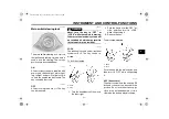
The hazard lights are used in case of
an emergency or to warn other drivers
when your vehicle is stopped where it
might be a traffic hazard.

NOTICE

ECA10061

Do not use the hazard lights for an
extended length of time with the en-
gine not running, otherwise the bat-
tery may discharge.

EAU12780

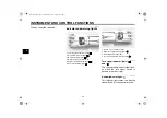
Cruise control switches 

See page 4-5 for an explanation of the
cruise control system.

EAU12820

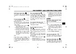
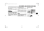
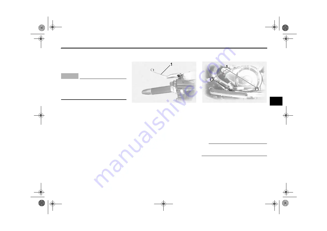
Clutch lever 

The clutch lever is located at the left
handlebar grip. To disengage the
clutch, pull the lever toward the handle-
bar grip. To engage the clutch, release
the lever. The lever should be pulled
rapidly and released slowly for smooth
clutch operation.
The clutch lever is equipped with a
clutch switch, which is part of the igni-
tion circuit cut-off system. (See page
4-20.)

EAU12880

Shift pedal 

The shift pedal is located on the left
side of the engine and is used in com-
bination with the clutch lever when
shifting the gears of the 5-speed con-
stant-mesh transmission equipped on
this motorcycle.

TIP

Use your toes or heel to shift up and
your toes to shift down.

1. Clutch lever

1. Shift pedal

U2C913E0.book  Page 9  Wednesday, June 11, 2008  1:03 PM

Summary of Contents for XVZ13TFSY

Page 1: ...DIC183 2C9 28199 13 XVZ13TFY C XVZ13TFSY C OWNER S MANUAL Read this manual carefully before operating this vehicle LIT 11626 22 50 ...

Page 2: ...EAU10042 Read this manual carefully before operating this vehicle This manual should stay with this vehicle if it is sold U2C913E0 book Page 1 Wednesday June 11 2008 1 03 PM ...

Page 3: ...To maintain these high standards it is important that you and your Yamaha dealer pay close attention to the recommended maintenance schedules and operating instructions contained within this manual Yamaha continually seeks advancements in product design and quality Therefore while this manual contains the most cur rent product information available at the time of printing there may be minor discre...

Page 4: ...ey all safety messages that follow this symbol to avoid possible injury or death A WARNING indicates a hazardous situation which if not avoided could result in death or serious injury A NOTICE indicates special precautions that must be taken to avoid damage to the vehicle or other property A TIP provides key information to make procedures easier or clearer WARNING NOTICE TIP U2C913E0 book Page 1 W...

Page 5: ... Yamaha Motor Corporation U S A 1st edition May 2008 All rights reserved Any reprinting or unauthorized use without the written permission of Yamaha Motor Corporation U S A is expressly prohibited Printed in Japan P N LIT 11626 22 50 U2C913E0 book Page 2 Wednesday June 11 2008 1 03 PM ...

Page 6: ... settings 5 6 Cassette deck operation 5 9 Radio operation 5 11 Optional CD changer operation 5 15 CB radio operation 5 16 Auxiliary audio source operation 5 20 FOR YOUR SAFETY PRE OPERATION CHECKS 6 1 Pre operation check list 6 2 OPERATION AND IMPORTANT RIDING POINTS 7 1 Starting and warming up a cold engine 7 1 Starting a warm engine 7 2 Shifting 7 3 Engine break in 7 4 Parking 7 5 PERIODIC MAINT...

Page 7: ...8 29 Checking the front fork 8 30 Checking the steering 8 30 Checking the wheel bearings 8 31 Battery 8 31 Replacing the fuses 8 32 Replacing the headlight bulb 8 34 Replacing a turn signal light bulb or the tail brake light bulb 8 35 Supporting the motorcycle 8 35 Troubleshooting 8 36 Troubleshooting charts 8 37 MOTORCYCLE CARE AND STORAGE 9 1 Matte color caution 9 1 Cleaning 9 1 Storage 9 2 SPEC...

Page 8: ... vehicle They contain important information for safe and proper operation of your vehicle Never remove any labels from your vehicle If a label becomes difficult to read or comes off a replacement label is available from your Yamaha dealer U2C913E0 book Page 1 Wednesday June 11 2008 1 03 PM ...

Page 9: ...TANT LABELS 1 2 1 1 5 3 2 4 CALIFORNIA ONLY NOTICE Cleaning with alkaline or acid cleaner gasoline or solvent will damage windshield Use neutral detergent 4B5 2815K 00 U2C913E0 book Page 2 Wednesday June 11 2008 1 03 PM ...

Page 10: ...assenger The failure of motorists to detect and recognize motorcycles in traf fic is the predominating cause of automobile motorcycle accidents Many accidents have been caused by an automobile driver who did not see the motorcycle Making yourself conspicuous appears to be very effective in reducing the chance of this type of accident Therefore Wear a brightly colored jacket Use extra caution when ...

Page 11: ... contribute to an impairment of vision that could delay seeing a hazard The use of a jacket heavy boots trousers gloves etc is effective in preventing or reducing abrasions or lacerations Never wear loose fitting clothes otherwise they could catch on the control levers footrests or wheels and cause injury or an accident Always wear protective clothing that covers your legs ankles and feet The engi...

Page 12: ...of the motorcycle to minimize imbalance or instabili ty Shifting weights can create a sud den imbalance Make sure that ac cessories and cargo are securely attached to the motorcycle before riding Check accessory mounts and cargo restraints frequently Properly adjust the suspension for your load suspension ad justable models only and check the condition and pres sure of your tires Never attach any ...

Page 13: ...ght distribution or aerody namic changes If accessories are added to the handlebar or front fork area they must be as lightweight as possible and should be kept to a minimum Bulky or large accessories may seriously affect the stability of the motorcycle due to aerody namic effects Wind may at tempt to lift the motorcycle or the motorcycle may become un stable in cross winds These ac cessories may ...

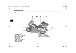
Page 14: ... 13 3 Fuel tank cap page 4 10 4 Fuel cock page 4 12 5 Battery page 8 31 6 Coolant reservoir page 8 17 7 Fuse box 2 page 8 32 8 Sidecase page 4 15 9 Helmet holder page 4 15 10 Tail brake light page 8 35 11 Rear turn signal light page 8 35 U2C913E0 book Page 1 Wednesday June 11 2008 1 03 PM ...

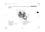
Page 15: ... seat 6 Shock absorber assembly air valve page 4 18 7 Rider seat page 4 14 8 Fuel tank page 4 10 9 Front fork air valve page 4 17 10 Headlight page 8 34 11 Front turn signal position lights page 8 35 12 Fuse box 1 page 8 32 13 Brake pedal page 4 10 14 Rider footrest 15 Passenger footrest U2C913E0 book Page 2 Wednesday June 11 2008 1 03 PM ...

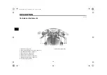
Page 16: ...radio control unit page 5 3 3 Left handlebar switches page 4 7 4 Rider headset jack page 5 2 5 Speedometer unit page 4 4 6 Main switch steering lock page 4 1 7 Right handlebar switches page 4 7 8 Throttle grip page 8 20 9 Brake lever page 4 10 U2C913E0 book Page 3 Wednesday June 11 2008 1 03 PM ...

Page 17: ...the electrical systems will be switched off which may result in loss of control or an accident EAU10691 LOCK The steering is locked and all electrical systems are off The key can be re moved To lock the steering 1 Turn the handlebars all the way to the left or right 2 Push the key in from the OFF po sition and then turn it to LOCK while still pushing it 3 Remove the key To unlock the steering Push...

Page 18: ...ral indicator light This indicator light comes on when the transmission is in the neutral position 1 Left turn signal indicator light 2 High beam indicator light 3 Oil level warning light 4 Overdrive indicator light O D 5 Engine trouble warning light 6 Fuel level warning light 1 Cruise control indicator lights 2 Right turn signal indicator light 3 Neutral indicator light 4 Coolant temperature warn...

Page 19: ...e control indicator lights See page 4 5 for an explanation of these indicator lights EAU11412 Coolant temperature warning light This warning light comes on if the en gine overheats If this occurs stop the engine immediately and allow the en gine to cool The electrical circuit of the warning light can be checked according to the follow ing procedure 1 Set the engine stop switch to and turn the key ...

Page 20: ...ushing the SELECT button switches the display between the odometer mode ODO and the tripmeter modes TRIP 1 and TRIP 2 in the following order ODO TRIP 1 TRIP 2 ODO If the fuel level warning light comes on see page 4 2 the odometer display will automatically change to the fuel re serve tripmeter mode TRIP F and start counting the distance traveled from that point In that case pushing the SELECT butt...

Page 21: ...y seg ments of the fuel meter disappear to wards E Empty as the fuel level decreases When only one segment is left near E Empty refuel as soon as possible When the key is turned to ON all of the display segments of the fuel meter will appear one after the oth er and then disappear in order to test the electrical circuit TIP This fuel meter is equipped with a self diagnosis system If a problem is d...

Page 22: ...system will re turn to the set speed after the throttle grip is released However if the speed is increased by more than 8 km h 5 mi h the cruise control system will be deactivated until the traveling speed is within 8 km h 5 mi h of the set speed Deactivating the cruise control sys tem Applying the front or rear brake or dis engaging the clutch will automatically deactivate the cruise control syst...

Page 23: ...stem off and have a Yamaha deal er check it EAU12092 Self diagnosis device This model is equipped with a self diag nosis device for various electrical cir cuits If a problem is detected in any of those circuits the engine trouble warning light will come on or flash If this occurs have a Yamaha dealer check the vehi cle NOTICE ECA11170 To prevent engine damage be sure to consult a Yamaha dealer as ...

Page 24: ... so that the turn signal lights will not self cancel while you are stopped at an intersec tion EAU12500 Horn switch Press this switch to sound the horn EAU12660 Engine stop switch Set this switch to before starting the engine Set this switch to to stop the engine in case of an emergen cy such as when the vehicle overturns or when the throttle cable is stuck EAU12711 Start switch Push this switch t...

Page 25: ...bar grip To disengage the clutch pull the lever toward the handle bar grip To engage the clutch release the lever The lever should be pulled rapidly and released slowly for smooth clutch operation The clutch lever is equipped with a clutch switch which is part of the igni tion circuit cut off system See page 4 20 EAU12880 Shift pedal The shift pedal is located on the left side of the engine and is...

Page 26: ...o remove the fuel tank cap Slide the lock cover open insert the key into the lock and then turn it 1 4 turn clockwise The lock will be released and the fuel tank cap can be removed To install the fuel tank cap 1 Insert the fuel tank cap into the tank opening with the key inserted in the lock and with the mark facing forward 2 Turn the key counterclockwise to the original position remove it and the...

Page 27: ...y of sparks open flames or other sources of ignition such as the pilot lights of water heaters and clothes dryers 2 Do not overfill the fuel tank Stop filling when the fuel reaches the bottom of the filler tube Because fuel expands when it heats up heat from the engine or the sun can cause fuel to spill out of the fuel tank 3 Wipe up any spilled fuel immedi ately NOTICE Immediately wipe off spille...

Page 28: ...ts Gasohol There are two types of gasohol gaso hol containing ethanol and that contain ing methanol Gasohol containing ethanol can be used if the ethanol con tent does not exceed 10 E10 Gas ohol containing methanol is not recommended by Yamaha because it can cause damage to the fuel system or vehicle performance problems EAU13550 Fuel cock The fuel cock supplies fuel from the tank to the carbureto...

Page 29: ...this position if you run out of fuel while riding When this occurs refuel as soon as possible and be sure to turn the fuel cock lever back to ON EAU13600 Starter choke knob Starting a cold engine requires a richer air fuel mixture which is supplied by the starter choke Move the knob in direction a to turn on the starter choke Move the knob in direction b to turn off the starter choke 1 Pointed end...

Page 30: ...ackets are aligned and then lock the steering with a suitable pad lock EAU14240 Rider seat To remove the rider seat Remove the nuts and then pull the rid er seat up To install the rider seat Insert the projection on the rear of the rider seat into the seat holder as shown place the seat in the original po sition and then tighten the nuts TIP Make sure that the rider seat is properly secured before...

Page 31: ...ossibly an accident or personal injury See pages 2 1 and 8 21 for important loading and tire pressure informa tion Always securely close the side cases and travel trunk before riding Distribute weight evenly on each side of the motorcycle Do not exceed the load limit of 9 kg 20 lb for each sidecase and the travel trunk Do not exceed the maximum load of 190 kg 419 lb for the ve hicle Do not exceed ...

Page 32: ...des of the lid down so that both latches snap into place Travel trunk To open the travel trunk 1 Insert the key into the lock turn it counterclockwise and then push it in 2 Fold the travel trunk lid up and then release it so that it will rest in place as shown NOTICE Do not apply excessive pressure on the travel trunk lid when it is open ECA10911 1 Sidecase lock 2 Unlock 1 Storage compartment 2 St...

Page 33: ...ing the lid EAU14653 Adjusting the front fork WARNING EWA10180 Always adjust both fork legs equal ly otherwise poor handling and loss of stability may result This front fork is equipped with air valves for adjusting the spring rate NOTICE ECA10091 To avoid damaging the front fork oil seals do not exceed the maximum air pressure Adjust the spring rate as follows 1 Place the vehicle on the sidestand...

Page 34: ...orber assembly This shock absorber assembly is equipped with an air valve for adjusting the spring rate NOTICE ECA10101 To avoid damaging the mechanism do not attempt to turn beyond the maximum or minimum settings Adjust the spring rate as follows 1 Place the vehicle on the sidestand When checking and adjusting the air pressure there should be no weight on the vehicle 2 Remove the air valve cap 1 ...

Page 35: ...ion circuit cut off system which cuts the ignition in certain situations See further down for an explanation of the ignition circuit cut off system WARNING EWA10240 The vehicle must not be ridden with the sidestand down or if the side stand cannot be properly moved up or does not stay up otherwise the sidestand could contact the ground and distract the operator resulting in a possible loss of cont...

Page 36: ...d is up but the clutch lever is not pulled It prevents starting when the trans mission is in gear and the clutch le ver is pulled but the sidestand is still down It cuts the running engine when the transmission is in gear and the sid estand is moved down Periodically check the operation of the ignition circuit cut off system according to the following procedure TIP This check is most reliable if p...

Page 37: ...0 Move the sidestand up 11 Keep the clutch lever pulled 12 Push the start switch Does the engine start The system is OK The motorcycle can be ridden The neutral switch may not be working correctly The motorcycle should not be ridden until checked by a Yamaha dealer The sidestand switch may not be working correctly The motorcycle should not be ridden until checked by a Yamaha dealer The clutch swit...

Page 38: ...oth erwise the battery may discharge WARNING EWA11051 To prevent electrical shock or short circuiting make sure that the caps are installed when the auxiliary DC jack and connector are not being used 12 V accessories connected to the auxiliary DC jack at the front and auxil iary DC connector under the rider seat can be used when the key is in the ACC or ON position 1 Auxiliary DC jack 1 Auxiliary ...

Page 39: ...nt speaker 3 Rider headset jack 4 Cassette deck lid 5 Main switch steering lock 6 Eject button 7 Cassette deck compartment 8 Auxiliary audio input jack 9 Rear speaker 10 Passenger volume control knob 11 Passenger TALK button 12 Passenger headset jack U2C913E0 book Page 1 Wednesday June 11 2008 1 03 PM ...

Page 40: ... good prac tice to cover them with a plastic bag when washing the motor cycle When cleaning the control unit display use a neutral detergent Never use strong abrasive cleaning products fuel gaso line thinner etc EAU15450 Headsets optional For CB Citizens Band radio transmis sion a headset is necessary however CB reception is possible without a headset For intercom use two head sets are necessary C...

Page 41: ...irection Tuning in a radio station automati cally Selecting a CD in the optional CD changer Audio system button AUDIO This button is used to perform the fol lowing operations Short push less than one second Turning on the audio system Changing the audio source in the following sequence Long push one second or more Turning off the audio system Selection button SELECT This button is used to perform ...

Page 42: ...ning on off the audio system To turn the power on 1 Make sure that the key is in the ACC or ON position 2 Push the AUDIO button once for less than one second To turn the power off Push the AUDIO button once for one second or more Output BASS TREB FAD Auto volume Intercom volume Radio SP HS Treble frequency Fade 1 2 IC AV 1 2 This mode does not appear in the display when the headsets are selected a...

Page 43: ...t the key is in the ACC or ON position 2 Push the CB button once for less than one second The current CB channel appears in the display To turn the power off Push the CB button once for one sec ond or more The CB indicator light will go off Adjusting the CB reception volume Turn the control knob until the desired CB reception volume is displayed e g Vo 10 The CB reception volume can be set between...

Page 44: ... While the selected mode is dis played for about five seconds re peatedly push either side of the up down switch for less than one second until the desired setting is displayed Selecting the output speakers or headsets 1 Repeatedly push the SELECT button for less than one second until either SP speakers or HS and headsets appears in the display 2 Push either side of the up down switch for less tha...

Page 45: ...y push either side of the up down switch for less than one second until the desired level is displayed The treble level can be set between 6 and 6 Adjusting the fade level balance be tween front and rear speakers 1 Make sure that the speakers are selected as the output source See the Selecting the output section 2 Repeatedly push the SELECT button for less than one second until FAD appears at the ...

Page 46: ...pensates for external noise 1 Repeatedly push the SELECT button for less than one second until the auto volume e g AV 3 appears in the display 2 Repeatedly push either side of the up down switch for less than one second until the desired volume is displayed The auto volume can be set between 0 and 5 Turning on off the CB roger beep 1 Repeatedly push the SELECT button for less than one second until...

Page 47: ...low the inside of the cassette deck to get wet If this happens keep the cassette deck lid open and dry out the deck in the shade To clean the tape head use a de magnetizing cleaning cas sette but be sure to turn the vol ume all the way down to avoid speaker damage Playing a cassette tape 1 Make sure that the audio system is turned on See page 5 3 2 Insert a cassette tape into the cas sette compart...

Page 48: ...P The maximum number of songs that can be skipped in either direc tion is 9 To stop skipping songs push the up down switch in the opposite di rection that songs are being skipped Skipping a blank When there is a long blank portion of tape on the cassette BLS appears in the display and the cassette deck auto matically fast forwards the tape to the next song Changing the tape play direction While th...

Page 49: ...TIP The Dolby noise reduction system has been manufactured under li cense from Dolby Laboratories Li censing Corporation Dolby and the double D symbol are registered trademarks of Dolby Laboratories Licensing Corpora tion Ejecting the cassette tape Push the eject button to eject the tape from the cassette deck EJCT appears in the display and then CASS starts flashing EAU15533 Radio operation 1 Eje...

Page 50: ...nd one AM band Since all three FM bands cover the whole FM frequency range any one of them can be selected for tuning in an FM station These three FM bands are useful for categorizing FM preset stations Repeatedly push the AUDIO button for less than one second until the desired frequency band appears in the display Tuning in a radio station automati cally 1 Select a frequency band See the Selectin...

Page 51: ...s for AM Tuning in a preset radio station 1 Select a frequency band See the Selecting a frequency band sec tion 2 Repeatedly push either side of the up down switch for less than one second until the desired preset station number is displayed TIP To be able to tune in a preset radio sta tion you must have previously pro grammed at least one See the following sections Programming preset radio statio...

Page 52: ...tune in a station automati cally 4 Repeatedly push either side of the up down switch for less than one second until the desired preset number 1 through 6 is dis played 5 Push the SELECT button once for less than one second to store the radio station selected in step 3 under the preset number selected in step 4 6 Repeat this procedure to preset other radio stations Programming preset radio stations...

Page 53: ... ty An optional six disc CD changer can be mounted in the travel trunk Ask a Yamaha dealer to install the genuine Clarion CDC635 model Playing a CD 1 Insert up to six CDs into the CD changer Follow the manufactur er s directions 2 Push the AUDIO button until as well as the CD num ber and track number e g 6 3 appear in the display The CD starts playing TIP 6 3 indicates track no 3 on CD no 6 Select...

Page 54: ...nough level to be aware of traf fic conditions and ensure safe ty Never ride the motorcycle with the CB antenna folded down TIP The antenna can be folded down after lifting the sleeve This CB radio will operate on any of the 40 frequencies designated as Citizens band channels by the Federal Commu nications Commission F C C This model features a frequency synthesiz ing circuit with PHASE LOCK LOOP ...

Page 55: ...n no lessening of the operating privileges or responsibilities of CB users An opera tor of a CB radio station is still required to comply with the Communications Act and with the rules of CB Radio Service CB radio functions The CB radio is capable of the following functions which are further explained in the following sections Selecting a CB channel for trans mitting or receiving Adjusting the squ...

Page 56: ...rs in the dis play For maximum reception sensitivity the squelch level should be set by turning the control knob fully counterclockwise and then slowly turning it clockwise un til the background noise has been suffi ciently reduced In order for an incoming CB signal to be heard it must be stronger than the noise received Turning the control further clockwise will increase the threshold level that ...

Page 57: ...equirements applicable to equipment operating in the Citizens Radio Service it is not to be used for any other purpose Channel Channel Frequency in MHz Channel Channel Frequency in MHz 1 26 965 21 27 215 2 26 975 22 27 225 3 36 985 23 27 235 4 27 005 24 27 245 5 27 015 25 27 255 6 27 025 26 27 265 7 27 035 27 27 275 8 27 055 28 27 285 9 27 065 29 27 295 10 27 075 30 27 305 11 27 085 31 27 315 12 2...

Page 58: ...a tion Auxiliary audio equipment can be con nected to and played through the au dio system 1 Insert the output plug of the auxil iary equipment into the jack locat ed at the right of the cassette deck 2 Repeatedly push the AUDIO but ton for less than one second until AUX appears in the display The auxiliary equipment can now be played through the audio system 1 TALK switch 1 Passenger TALK button ...

Page 59: ...AUDIO SYSTEM AND CB RADIO 5 21 5 U2C913E0 book Page 21 Wednesday June 11 2008 1 03 PM ...

Page 60: ...d in the Owner s Manual WARNING EWA11151 Failure to inspect or maintain the vehicle properly increases the possibility of an accident or equipment damage Do not operate the vehicle if you find any problem If a problem cannot be corrected by the procedures provided in this manual have the vehicle inspected by a Yamaha dealer Before using this vehicle check the following points U2C913E0 book Page 1 ...

Page 61: ...ng system for leakage 8 17 Front brake Check operation If soft or spongy have Yamaha dealer bleed hydraulic system Check lever free play Adjust if necessary Check brake pads for wear Replace if necessary Check fluid level in reservoir If necessary add recommended brake fluid to specified level Check hydraulic system for leakage 8 24 8 25 8 25 Rear brake Check operation If soft or spongy have Yamah...

Page 62: ...ition and tread depth Check air pressure Correct if necessary 8 21 8 23 Brake and shift pedals Make sure that operation is smooth Lubricate pedal pivoting points if necessary 8 28 Brake and clutch levers Make sure that operation is smooth Lubricate lever pivoting points if necessary 8 28 Sidestand Make sure that operation is smooth Lubricate pivot if necessary 8 29 Chassis fasteners Make sure that...

Page 63: ...A16060 The engine trouble warning light should come on for a few seconds then go off If a warn ing light does not go off see page 4 2 for the corresponding warning light circuit check If the fuel level warning light comes on check the fuel level and if necessary refuel as soon as possible 3 Shift the transmission into the neu tral position See page 7 3 The neutral indicator light should come on If...

Page 64: ...ec trical circuit 6 After starting the engine move the starter choke back halfway NOTICE For maximum engine life always warm the engine up before starting off Never accel erate hard when the engine is cold ECA11131 7 When the engine is warm turn the starter choke off TIP The engine is warm when it responds normally to the throttle with the starter choke turned off To avoid the possi bility of exce...

Page 65: ...ut and accelerate 1 Pull the clutch lever to disengage the clutch 2 Shift the transmission into first gear The neutral indicator light should go out 3 Open the throttle gradually and at the same time release the clutch lever slowly 4 At the recommended shift points shown in the following table close the throttle and at the same time quickly pull the clutch lever in 5 Shift the transmission into se...

Page 66: ...nces During this period prolonged full throt tle operation or any condition that might result in engine overheating must be avoided EAU17043 0 1000 km 0 600 mi Avoid prolonged operation above 1 3 throttle NOTICE After 1000 km 600 mi of operation the engine oil and final gear oil must be changed and the oil filter cartridge or element re placed ECA10332 1000 1600 km 600 1000 mi Avoid prolonged oper...

Page 67: ...ce the engine and exhaust system can become very hot park in a place where pedestri ans or children are not likely to touch them and be burned Do not park on a slope or on soft ground otherwise the vehicle may overturn increasing the risk of a fuel leak and fire Do not park near grass or other flammable materials which might catch fire U2C913E0 book Page 5 Wednesday June 11 2008 1 03 PM ...

Page 68: ...nning engine has moving parts that can catch on body parts or clothing and electrical parts that can cause shocks or fires Running the engine while ser vicing can lead to eye injury burns fire or carbon monoxide poisoning possibly leading to death See page 2 1 for more in formation about carbon monox ide EAU17302 Emission controls not only function to ensure cleaner air but are also vital to prope...

Page 69: ...n the owner s tool kit are intended to assist you in the performance of preventive maintenance and minor repairs How ever additional tools such as a torque wrench may be necessary to perform certain maintenance work correctly TIP If you do not have the tools or experi ence required for a particular job have a Yamaha dealer perform it for you 1 Owner s tool kit U2C913E0 book Page 2 Wednesday June 1...

Page 70: ...cessary 2 Fuel filter Replace Replace 3 Spark plugs Check condition Adjust gap and clean Replace every 8000 mi 13000 km or 12 months Replace Replace 4 Valve clearance Check and adjust valve clearance when engine is cold Every 26600 mi 42000 km 5 Crankcase breather system Check breather hose for cracks or damage Replace if necessary 6 Carburetor synchro nization Adjust synchronization of carbu reto...

Page 71: ... fluid leak age Correct if necessary 3 Front brake Check operation fluid level and for fluid leakage Adjust brake lever free play and replace brake pads if necessary 4 Rear brake Check operation fluid level and for fluid leakage Replace brake pads if necessary 5 Brake hoses Check for cracks or damage Replace Every 4 years 6 Wheels Check runout and for damage Replace if necessary 7 Tires Check trea...

Page 72: ...Apply silicone grease lightly 13 Brake pedal pivot shaft Apply lithium soap based grease lightly 14 Clutch lever pivot shaft Apply silicone grease lightly 15 Shift pedal pivot shaft Apply lithium soap based grease lightly 16 Sidestand pivot Check operation Apply lithium soap based grease lightly 17 Sidestand switch Check operation and replace if necessary No ITEM ROUTINE INITIAL ODOMETER READINGS ...

Page 73: ...y Change with ethylene glycol anti freeze coolant every 24 months Change 24 Final gear oil Check oil level and for oil leakage Change at initial 600 mi 1000 km or 1 month and thereafter every 16000 mi 25000 km or 24 months Change Change 25 Front and rear brake switches Check operation 26 Control cables Apply Yamaha chain and cable lube or engine oil thoroughly No ITEM ROUTINE INITIAL ODOMETER READ...

Page 74: ... fluid levels and fill the reservoirs as required Replace the oil seals on the inner parts of the brake or clutch master cylinders caliper cylinders and clutch release cylinder every two years Replace the brake and clutch hoses every four years or if cracked or damaged 27 Throttle grip hous ing and cable Check operation and free play Adjust the throttle cable free play if necessary Lubricate the t...

Page 75: ...o be re moved and installed EAU35841 Cowling A To remove the cowling 1 Remove the bolts 2 Remove the quick fastener screw by turning it 1 4 turn counterclock wise and then take the cowling off To install the cowling Place the cowling in the original posi tion and then install the quick fastener screw and the bolts 1 Cowling A 2 Panel A 1 Cowling B 2 Panel B 3 Panel C 1 Cowling A 2 Bolt 3 Quick fas...

Page 76: ...shown To install the cowling 1 Place the cowling in the original position and then install the bolts TIP Make sure that the projection fits into the grommet 2 Install cowling A EAU35860 Panels A and B To remove one of the panels Remove the bolt and then pull the pan el off as shown 1 Grommet 2 Projection 3 Cowling A 1 Cowling B 2 Bolt 1 Bolt 1 Panel A 2 Bolt U2C913E0 book Page 9 Wednesday June 11 ...

Page 77: ...el B 2 Remove the left passenger foot rest by removing the bolts 3 Remove the screw and then pull the panel off as shown To install the panel 1 Place the panel in the original posi tion and then install the screw 2 Install the passenger footrest by installing the bolts 3 Install panel B 1 Panel B 2 Bolt 1 Panel C 2 Screw 3 Bolt U2C913E0 book Page 10 Wednesday June 11 2008 1 03 PM ...

Page 78: ...e center electrode on each spark plug is a medium to light tan the ideal color when the vehicle is ridden normally 2 Check that all spark plugs installed in the engine have the same color TIP If any spark plug shows a distinctly dif ferent color the engine could be oper ating improperly Do not attempt to diagnose such problems yourself In stead have a Yamaha dealer check the vehicle 3 Check each s...

Page 79: ... cracks or damage Replace if dam aged Make sure the vent hose is not blocked Clean it if necessary EAU19907 Engine oil and oil filter car tridge The engine oil level should be checked before each ride In addition the oil must be changed and the oil filter car tridge replaced at the intervals speci fied in the periodic maintenance and lubrication chart To check the engine oil level 1 Place the vehi...

Page 80: ...he engine to collect the used oil 4 Remove the engine oil filler cap and drain bolt to drain the oil from the crankcase TIP Skip steps 5 7 if the oil filter cartridge is not being replaced 5 Remove the oil filter cartridge with an oil filter wrench TIP An oil filter wrench is available at a Yamaha dealer 6 Apply a thin coat of clean engine oil to the O ring of the new oil filter cartridge 1 Engine...

Page 81: ...o prevent clutch slip page since the engine oil also lubricates the clutch do not mix any chemical additives Do not use oils with a diesel speci fication of CD or oils of a high er quality than specified In addition do not use oils labeled ENERGY CONSERVING II or higher Make sure that no foreign mate rial enters the crankcase 1 O ring 1 Torque wrench 2 Oil filter wrench Tightening torque Oil filte...

Page 82: ...ed for oil leakage before each ride If any leakage is found have a Yamaha deal er check and repair the vehicle In addi tion the final gear oil level must be checked and the oil changed as follows at the intervals specified in the periodic maintenance and lubrication chart WARNING EWA10370 Make sure that no foreign mate rial enters the final gear case Make sure that no oil gets on the tire or wheel...

Page 83: ...n bolt and then tighten it to the specified torque 4 Refill with the recommended final gear oil to the brim of the filler hole TIP GL4 is a quality rating Hypoid gear oils rated GL5 or GL6 may also be used 5 Install the oil filler bolt and then tighten it to the specified torque 6 Check the final gear case for oil leakage If oil is leaking check for the cause 1 Final gear oil filler bolt 2 Final g...

Page 84: ...at See page 4 14 open the reservoir cap add coolant to the maximum level mark and then close the reservoir cap and install the rider seat WARNING Re move only the coolant reservoir cap Never attempt to remove the radiator cap when the en gine is hot EWA15161 NOTICE If coolant is not available use dis tilled water or soft tap water in stead Do not use hard water or salt water since it is harmful to...

Page 85: ...n the periodic maintenance and lubrication chart Clean or if necessary replace the air filter elements more frequently if you are riding in unusually wet or dusty areas 1 Remove cowlings A and B See page 8 8 TIP Continue as follows for each air filter el ement 2 Remove the air filter case bolts 3 Loosen the air filter case joint clamp screw and then pull the air filter case off 4 Remove the air fi...

Page 86: ...r element is properly seated in the air filter case The engine should never be operat ed without the air filter element installed otherwise the pis ton s and or cylinder s may become excessively worn ECA10481 8 Install the air filter case cover by in stalling the screws 9 Push the air filter case onto the air filter case joint and then tighten the clamp screw 10 Install the air filter case bolts 1...

Page 87: ...nowledge and experience EAU44733 Checking the engine idling speed Check the engine idling speed and if necessary have it adjusted by a Yamaha dealer EAU21382 Checking the throttle cable free play The throttle cable free play should mea sure 4 0 6 0 mm 0 16 0 24 in at the throttle grip Periodically check the throttle cable free play and if neces sary have a Yamaha dealer adjust it Engine idling spe...

Page 88: ...im proper tire pressure may cause se vere injury or death from loss of control The tire air pressure must be checked and adjusted on cold tires i e when the temperature of the tires equals the ambient temperature The tire air pressure must be ad justed in accordance with the riding speed and with the total weight of rider passenger car go and accessories approved for this model WARNING EWA10511 Ne...

Page 89: ...be left to a Yamaha dealer Tire information This motorcycle is equipped with cast wheels and tubeless tires WARNING EWA10461 The front and rear tires should be of the same make and design other wise the handling characteristics of the vehicle may be different which could lead to an accident After extensive tests only the tires list ed below have been approved for this model by Yamaha Motor Co Ltd ...

Page 90: ...oken in for it to develop its optimal characteris tics After repairing or replacing the rear tire tighten the valve stem nut and locknut to the specified torques EAU22073 Clutch lever Since this model is equipped with a hy draulic clutch adjusting the clutch lever free play is not needed However it is necessary to check the clutch fluid level and check the hydraulic system for leakage before each ...

Page 91: ...ft or spongy feeling in the brake lever can indicate the presence of air in the hydraulic system If there is air in the hy draulic system have a Yamaha dealer bleed the system before operating the motorcycle Air in the hydraulic system will dimin ish the braking performance which may result in loss of con trol and an accident EAU22280 Adjusting the rear brake light switch The rear brake light swit...

Page 92: ...indicator grooves have almost disap peared have a Yamaha dealer replace the brake pads as a set EAU22470 Rear brake pads Each rear brake pad is provided with a wear indicator groove which allows you to check the brake pad wear with out having to disassemble the brake To check the brake pad wear check the wear indicator groove If a brake pad has worn to the point that the wear indicator groove has ...

Page 93: ...commended quality brake fluid otherwise the rubber seals may deteriorate causing leakage and poor braking or clutch performance Refill with the same type of brake fluid Mixing fluids may result in a harmful chemical reaction and lead to poor braking or clutch per formance Be careful that water does not en ter the brake or clutch fluid reser voir when refilling Water will significantly lower the bo...

Page 94: ...trol cables and the condition of the cables should be checked before each ride and the ca bles and cable ends should be lubricat ed if necessary If a cable is damaged or does not move smoothly have a Yamaha dealer check or replace it WARNING Damage to the outer housing of cables may result in in ternal rusting and cause interfer ence with cable movement Replace damaged cables as soon as possi ble ...

Page 95: ...the pedal pivots should be lu bricated if necessary EAU43600 Checking and lubricating the brake and clutch levers The operation of the brake and clutch levers should be checked before each ride and the lever pivots should be lu bricated if necessary Recommended lubricant Lithium soap based grease Recommended lubricant Silicone grease U2C913E0 book Page 28 Wednesday June 11 2008 1 03 PM ...

Page 96: ...nd and distract the operator re sulting in a possible loss of control EAUM1650 Lubricating the swingarm piv ots The swingarm pivots must be lubricat ed at the intervals specified in the peri odic maintenance and lubrication chart EAU23250 Lubricating the rear suspen sion The pivoting points of the rear suspen sion must be lubricated at the intervals specified in the periodic maintenance and lubric...

Page 97: ...nt fork compresses and rebounds smoothly NOTICE ECA10590 If any damage is found or the front fork does not operate smoothly have a Yamaha dealer check or re pair it EAU23283 Checking the steering Worn or loose steering bearings may cause danger Therefore the operation of the steering must be checked as fol lows at the intervals specified in the pe riodic maintenance and lubrication chart 1 Place a...

Page 98: ... cell seals as this would permanent ly damage the battery WARNING EWA10760 Electrolyte is poisonous and dangerous since it contains sul furic acid which causes severe burns Avoid any contact with skin eyes or clothing and al ways shield your eyes when working near batteries In case of contact administer the fol lowing FIRST AID EXTERNAL Flush with plenty of water INTERNAL Drink large quan tities o...

Page 99: ... the battery 1 If the vehicle will not be used for more than one month remove the battery fully charge it and then place it in a cool dry place NOTICE When removing the battery be sure the key is turned to OFF then discon nect the negative lead before disconnecting the positive lead ECA16302 2 If the battery will be stored for more than two months check it at least once a month and fully charge it...

Page 100: ...rcuit in question to check if the device operates 4 If the fuse immediately blows again have a Yamaha dealer check the electrical system 1 Cruise control fuse 2 Carburetor heater fuse 3 Auxiliary DC connector fuse 4 Auxiliary DC jack fuse 5 Audio system fuse 6 Spare fuse 1 Backup fuse for odometer and clock 2 Radiator fan fuse 3 Headlight fuse 4 Signaling system fuse 5 Ignition fuse 6 Spare fuse S...

Page 101: ...any dirt and fingerprints on the headlight bulb using a cloth moistened with al cohol or thinner 1 Disconnect the headlight coupler and then remove the headlight bulb cover 2 Unhook the headlight bulb holder and then remove the burnt out bulb 3 Place a new headlight bulb into po sition and then secure it with the bulb holder 4 Install the headlight bulb cover and then connect the coupler 5 Have a ...

Page 102: ... removing the front and rear wheel or performing other maintenance requiring the motorcycle to stand up right Check that the motorcycle is in a stable and level position before starting any maintenance A strong wooden box can be placed under the engine for added stability To service the front wheel 1 Stabilize the rear of the motorcycle by using a motorcycle stand or if an additional motorcycle st...

Page 103: ... systems your self However should your motorcycle require any repair take it to a Yamaha dealer whose skilled technicians have the necessary tools experience and know how to service the motorcycle properly Use only genuine Yamaha replace ment parts Imitation parts may look like Yamaha parts but they are often inferi or have a shorter service life and can lead to expensive repair bills WARNING EWA1...

Page 104: ...eck the vehicle Remove the spark plugs and check the electrodes 3 Ignition Wipe off with a dry cloth and correct the spark plug gaps or replace the spark plugs Have a Yamaha dealer check the vehicle The engine does not start Have a Yamaha dealer check the vehicle The engine does not start Check the battery Operate the electric starter 4 Battery The engine turns over quickly The engine turns over s...

Page 105: ...ed press down on the cap while turning it counterclockwise and then remove the cap TIP If coolant is not available tap water can be temporarily used instead provided that it is changed to the recommended coolant as soon as possible Wait until the engine has cooled Check the coolant level in the reservoir and radiator The coolant level is OK The coolant level is low Check the cooling system for lea...

Page 106: ... quality plastic polishing com pound after washing Do not use any harsh chemical products on plastic parts Make sure to avoid using cloths or sponges which have been in contact with strong or abrasive cleaning products solvent or thinner fuel gasoline rust re movers or inhibitors brake flu id antifreeze or electrolyte Before cleaning the motorcycle 1 Cover the muffler outlets to pre vent water ent...

Page 107: ...ome cleaning compounds for plastics may leave scratches on the windshield Before using such clean ers test an area of the windshield which does not affect your visibility and which cannot be easily recognized After cleaning the motorcycle Apply Yamaha Silicone Wax or another high quality automotive type wax on all painted and chrome plated surfaces Avoid combination cleaner waxes since many contai...

Page 108: ...y from sparking make sure to ground the spark plug electrodes while turning the engine over EWA10951 e Remove the spark plug caps from the spark plugs and then install the spark plugs and the spark plug caps 6 Lubricate all control cables and the pivoting points of all levers and pedals as well as of the side stand centerstand 7 Check and if necessary correct the tire air pressure and then lift th...

Page 109: ...S qt 3 26 Imp qt Final gear oil Type SAE 80 API GL 4 Hypoid gear oil Quantity 0 20 L 0 21 US qt 0 18 Imp qt Cooling system Coolant reservoir capacity up to the maximum level mark 0 35 L 0 37 US qt 0 31 Imp qt Radiator capacity including all routes 3 50 L 3 70 US qt 3 08 Imp qt Air filter Air filter element Dry element Fuel Recommended fuel Unleaded gasoline only Fuel tank capacity 22 5 L 5 94 US g...

Page 110: ...ition 0 90 kg 0 198 lb Front 250 kPa 2 50 kgf cm 36 psi Rear 250 kPa 2 50 kgf cm 36 psi Loading condition 90 190 kg 198 419 lb Front 250 kPa 2 50 kgf cm 36 psi Rear 280 kPa 2 80 kgf cm 41 psi Front wheel Wheel type Cast wheel Rim size 16M C x MT3 50 Rear wheel Wheel type Cast wheel Rim size 15M C x MT4 00 Front brake Type Dual disc brake Operation Right hand operation Recommended fluid DOT 4 Rear ...

Page 111: ...ture warning light 12 V 1 7 W 1 Engine trouble warning light 12 V 1 7 W 1 Overdrive indicator light 12 V 1 7 W 1 Cruise control SET indicator light 12 V 1 7 W 1 Cruise control RES indicator light 12 V 1 7 W 1 Cruise control ON indicator light 12 V 1 7 W 1 Audio system amplifier Speaker output 14 W 4 Headset output 1 W 2 Auto volume range 5 steps Speaker impedance 4 Ω Headset impedance 8 16 Ω Fuses...

Page 112: ...entification number The key identification number is stamped into the key tag Record this number in the space provided and use it for reference when ordering a new key EAU26400 Vehicle identification number The vehicle identification number is stamped into the steering head pipe Record this number in the space pro vided TIP The vehicle identification number is used to identify your motorcycle and ...

Page 113: ...el is affixed to the frame under the rider seat See page 4 14 Record the information on this label in the space provided This information will be needed when ordering spare parts from a Yamaha dealer 1 Model label U2C913E0 book Page 2 Wednesday June 11 2008 1 03 PM ...

Page 114: ...and if it finds that a safety defect exists in a group of vehicles it may order a recall and remedy campaign However NHTSA cannot become involved in individual problems between you your dealer or Yamaha Motor Corporation U S A To contact NHTSA you may call the Vehicle Safety Hotline toll free at 1 888 327 4236 TTY 1 800 424 9153 go to http www safercar gov or write to Administrator NHTSA 400 Seven...

Page 115: ...icle for the purpose of noise control prior to its sale or delivery to the ultimate purchaser or while it is in use or 2 the use of the vehicle after such device or element of design has been removed or rendered inoperative by any person AMONG THOSE ACTS PRESUMED TO CONSTITUTE TAMPERING ARE THE ACTS LISTED BELOW These acts include tampering with the following systems i e modification removal etc E...

Page 116: ...nder that maintenance work is required It is not acceptable proof of maintenance work Maintenance interval Date of service Mileage Servicing dealer name and address Remarks 600 mi 1000 km or 1 month 4000 mi 7000 km or 6 months 8000 mi 13000 km or 12 months 12000 mi 19000 km or 18 months 16000 mi 25000 km or 24 months 20000 mi 31000 km or 30 months 24000 mi 37000 km or 36 months 28000 mi 43000 km o...

Page 117: ...MATION 11 6 11 36000 mi 55000 km or 54 months 40000 mi 61000 km or 60 months Maintenance interval Date of service Mileage Servicing dealer name and address Remarks U2C913E0 book Page 6 Wednesday June 11 2008 1 03 PM ...

Page 118: ...CONSUMER INFORMATION 11 7 11 EAU26703 YAMAHA MOTOR CORPORATION U S A ROYAL STAR VENTURE LIMITED WARRANTY U2C913E0 book Page 7 Wednesday June 11 2008 1 03 PM ...

Page 119: ...CONSUMER INFORMATION 11 8 11 U2C913E0 book Page 8 Wednesday June 11 2008 1 03 PM ...

Page 120: ...CONSUMER INFORMATION 11 9 11 U2C913E0 book Page 9 Wednesday June 11 2008 1 03 PM ...

Page 121: ...Final gear oil 8 15 Front and rear brake pads checking 8 25 Front fork adjusting 4 17 Front fork checking 8 30 Fuel 4 11 Fuel cock 4 12 Fuel level warning light 4 3 Fuel tank cap 4 10 Fuses replacing 8 32 H Handlebar switches 4 7 Hazard switch 4 8 Headlight bulb replacing 8 34 Headsets 5 2 Helmet holders 4 15 High beam indicator light 4 3 Horn switch 4 8 I Identification numbers 11 1 Ignition circ...

Page 122: ...e 8 35 Swingarm pivots lubricating 8 29 T TALK switch 4 8 Throttle cable free play checking 8 20 Throttle grip and cable checking and lubricating 8 27 Tires 8 21 Tool kit 8 2 Troubleshooting 8 36 Troubleshooting charts 8 37 Turn signal indicator lights 4 2 Turn signal light bulb or tail brake light bulb replacing 8 35 Turn signal switch 4 8 V Valve clearance 8 21 Vehicle identification number 11 1...

Page 123: ...U2C913E0 book Page 3 Wednesday June 11 2008 1 03 PM ...

Page 124: ...PRINTED IN JAPAN 2008 06 0 5 1 CR E PRINTED ON RECYCLED PAPER YAMAHA MOTOR CO LTD DIC183 ...

Reviews: