ENGINE
3-6
d. Measure the valve clearance with a thickness
gauge.
▲▲▲
▲
▲
▲▲▲
▲
▲
▲▲▲
▲
▲
▲▲▲
▲
▲
▲▲▲
▲
▲
▲▲▲
▲
▲▲▲
▼▼▼
▼
▼
▼▼▼
▼
▼
▼▼▼
▼
▼
▼▼▼
▼
▼
▼▼▼
▼
▼
▼▼▼
▼
▼▼▼
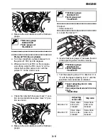
Piston #2 TDC (front cylinder)
a. Turn the crankshaft counterclockwise from
the piston #1 TDC by 408 degrees.
b. When piston #2 is at TDC on the compres-
sion stroke, align the TDC mark “e” on the
crankshaft position sensor rotor with the
pointer “b” on the clutch cover.
c. Check the camshaft drive gear mark “c” posi-
tion and camshaft driven gear mark “d” posi-
tion as shown.
d. Measure the valve clearance with a thickness
gauge.
▲▲▲
▲
▲
▲▲▲
▲
▲
▲▲▲
▲
▲
▲▲▲
▲
▲
▲▲▲
▲
▲
▲▲▲
▲
▲▲▲
12.Adjust:
• Valve clearance
▼▼▼
▼
▼
▼▼▼
▼
▼
▼▼▼
▼
▼
▼▼▼
▼
▼
▼▼▼
▼
▼
▼▼▼
▼
▼▼▼
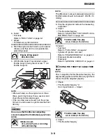
a. Loosen the locknut “1”.
b. Insert a thickness gauge “2” between the end
of the adjusting screw and the valve tip.
c. Turn the adjusting screw “3” in direction “a” or
“b” with the tappet adjusting tool “4” until the
specified valve clearance is obtained.
Thickness gauge
90890-03180
Feeler gauge set
YU-26900-9
d
c
b
e
d
c
Thickness gauge
90890-03180
Feeler gauge set
YU-26900-9
Thickness gauge
90890-03180
Feeler gauge set
YU-26900-9
Tappet adjusting tool (4 mm)
90890-04133
Valve adjustment wrench 3 mm &
4 mm
YM-08035-A
Adjusting
screw side
Slip side
Direction “a”
Valve clear-
ance is in-
creased.
Valve clear-
ance is de-
creased.
Direction “b”
Valve clear-
ance is de-
creased.
Valve clear-
ance is in-
creased.
1
Summary of Contents for XV19SW 2006
Page 6: ......
Page 8: ......
Page 24: ...SPECIAL TOOLS 1 15...
Page 55: ...LUBRICATION POINTS AND LUBRICANT TYPES 2 30...
Page 60: ...LUBRICATION SYSTEM CHART AND DIAGRAMS 2 35 D D B B D D C C A A B C C B 3 2 1 3 4 6 7 6 7 5...
Page 62: ...LUBRICATION SYSTEM CHART AND DIAGRAMS 2 37 A A A A 1 3 2 4...
Page 64: ...LUBRICATION SYSTEM CHART AND DIAGRAMS 2 39 A 1 2 3 4...
Page 66: ...LUBRICATION SYSTEM CHART AND DIAGRAMS 2 41 A A A 1 5 5 1 3 2 4 B B B B...
Page 68: ...LUBRICATION SYSTEM CHART AND DIAGRAMS 2 43 1 2...
Page 69: ...LUBRICATION SYSTEM CHART AND DIAGRAMS 2 44 1 Transfer gear oil pump 2 Middle driven shaft...
Page 78: ...CABLE ROUTING 2 53...
Page 86: ...CABLE ROUTING 2 61...
Page 89: ......
Page 122: ...ELECTRICAL SYSTEM 3 33 a b 1...
Page 125: ......


