background image

1

IDENTIFICATION NUMBERS

GEN

INFO

A80700-0*

IDENTIFICATION NUMBERS

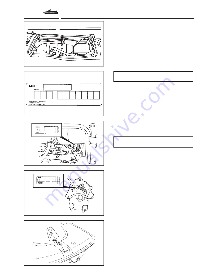
PRIMARY I.D. NUMBER
The primary I.D. number is stamped on a
plate attached to the hull on the front of the
engine hood.

Starting primary I.D. number:

F0M: 800101 –

ENGINE SERIAL NUMBER
The engine serial number is stamped on a
plate attached to the crankcase.

Starting serial number:

67E : 300101 –

PUMP SERIAL NUMBER
The jet pump unit serial number is stamped
on a plate attached to the intermediate hous-
ing.

HULL IDENTIFICATION NUMBER (H.I.N)
The H.I.N. is stamped on a plate attached to
the rear end of the footrest floor.

Summary of Contents for WaveRunner XL760

Page 1: ......

Page 2: ......

Page 3: ......

Page 4: ......

Page 5: ......

Page 6: ......

Page 7: ......

Page 8: ......

Page 9: ......

Page 10: ......

Page 11: ......

Page 12: ......

Page 13: ......

Page 14: ......

Page 15: ......

Page 16: ......

Page 17: ......

Page 18: ......

Page 19: ......

Page 20: ......

Page 21: ......

Page 22: ......

Page 23: ......

Page 24: ......

Page 25: ......

Page 26: ......

Page 27: ......

Page 28: ......

Page 29: ......

Page 30: ......

Page 31: ......

Page 32: ......

Page 33: ......

Page 34: ......

Page 35: ......

Page 36: ......

Page 37: ......

Page 38: ......

Page 39: ......

Page 40: ......

Page 41: ......

Page 42: ......

Page 43: ......

Page 44: ......

Page 45: ......

Page 46: ......

Page 47: ......

Page 48: ......

Page 49: ......

Page 50: ......

Page 51: ......

Page 52: ......

Page 53: ......

Page 54: ......

Page 55: ......

Page 56: ......

Page 57: ......

Page 58: ......

Page 59: ......

Page 60: ......

Page 61: ......

Page 62: ......

Page 63: ......

Page 64: ......

Page 65: ......

Page 66: ......

Page 67: ......

Page 68: ......

Page 69: ......

Page 70: ......

Page 71: ......

Page 72: ......

Page 73: ......

Page 74: ......

Page 75: ......

Page 76: ......

Page 77: ......

Page 78: ......

Page 79: ......

Page 80: ......

Page 81: ......

Page 82: ......

Page 83: ......

Page 84: ......

Page 85: ......

Page 86: ......

Page 87: ......

Page 88: ......

Page 89: ......

Page 90: ......

Page 91: ......

Page 92: ......

Page 93: ......

Page 94: ......

Page 95: ......

Page 96: ......

Page 97: ......

Page 98: ......

Page 99: ......

Page 100: ......

Page 101: ......

Page 102: ......

Page 103: ......

Page 104: ......

Page 105: ......

Page 106: ......

Page 107: ......

Page 108: ......

Page 109: ......

Page 110: ......

Page 111: ......

Page 112: ......

Page 113: ......

Page 114: ......

Page 115: ......

Page 116: ......

Page 117: ......

Page 118: ......

Page 119: ......

Page 120: ......

Page 121: ......

Page 122: ......

Page 123: ......

Page 124: ......

Page 125: ......

Page 126: ......

Page 127: ......

Page 128: ......

Page 129: ......

Page 130: ......

Page 131: ......

Page 132: ......

Page 133: ......

Page 134: ......

Page 135: ......

Page 136: ......

Page 137: ......

Page 138: ......

Page 139: ......

Page 140: ......

Page 141: ......

Page 142: ......

Page 143: ......

Page 144: ......

Page 145: ......

Page 146: ......

Page 147: ......

Page 148: ......

Page 149: ......

Page 150: ......

Page 151: ......

Page 152: ......

Page 153: ......

Page 154: ......

Page 155: ......

Page 156: ......

Page 157: ......

Page 158: ......

Page 159: ......

Page 160: ......

Page 161: ......

Page 162: ......

Page 163: ......

Page 164: ......

Page 165: ......

Page 166: ......

Page 167: ......

Page 168: ......

Page 169: ......

Page 170: ......

Page 171: ......

Page 172: ......

Page 173: ......

Page 174: ......

Page 175: ......

Page 176: ......

Page 177: ......

Page 178: ......

Page 179: ......

Page 180: ......

Page 181: ......

Page 182: ......

Page 183: ......

Page 184: ......

Page 185: ......

Page 186: ......

Page 187: ......

Page 188: ......

Page 189: ......

Page 190: ......

Page 191: ......

Page 192: ......

Page 193: ......

Page 194: ...SUPPLEMENTARY SERVICE MANUAL LIT 18616 02 00 F0M 28197 Z8 1X WaveRunner XL700 Marine ...

Page 195: ... please refer to the descriptions for XL760 in the above SERVICE MANUAL A10001 0 XL700 SUPPLEMENTARY SERVICE MANUAL 1998 Yamaha Motor Co Ltd 1st Edition September 1998 All rights reserved No part of this publication may be reproduced or transmitted in any from or by any means including photocopying and recording without the written permission of the copyright holder Such written permission must al...

Page 196: ...G 9 PERIODIC INSPECTION AND ADJUSTMENT MAINTANANCE INTERVAL CHART 11 PERIODIC SERVICE 12 FUEL SYSTEM 12 Trolling speed adjustment 12 Carburetor adjustment 12 FUEL SYSTEM FUEL LINE 13 EXPLODED DIAGRAM 13 REMOVAL AND INSTALLATION CHART 13 CARBURETOR REMOVAL 14 EXPLODED DIAGRAM 14 REMOVAL AND INSTALLATION CHART 14 CARBURETOR 16 EXPLODED DIAGRAM 16 REMOVAL AND INSTALLATION CHART 16 SERVICE POINTS 17 H...

Page 197: ... INSTALLATION CHART 25 CYLINDER 26 EXPLODED DIAGRAM 26 REMOVAL AND INSTALLATION CHART 26 SERVICE POINT 27 Cylinder inspection 27 PISTON 28 EXPLODED DIAGRAM 28 REMOVAL AND INSTALLATION CHART 28 SERVICE POINT 29 Piston inspection 29 FLYWHEEL MAGNETO AND BASE 30 EXPLODED DIAGRAM 30 REMOVAL AND INSTALLATION CHART 30 SERVICE POINTS 32 Coupling flange removal and installation 32 Flywheel magneto removal...

Page 198: ...M 46 WIRING DIAGRAM 46 CHARGING SYSTEM 47 WIRING DIAGRAM 47 RECTIFIER REGULATOR OUT PUT PEAK VOLTAGE 48 LIGHTING COIL OUT PUT PEAK VOLTAGE 48 INDICATION SYSTEM 49 WIRING DIAGRAM 49 OIL LEVEL SENSOR 50 OIL LEVEL WARNING LAMP 50 HULL AND HOOD THORTTLE CABLE AND CHOKE CABLE 51 EXPLODED DIAGRAM 51 REMOVAL AND INSTALLATION CHART 51 EXHAUST SYSTEM 52 EXPLODED DIAGRAM 52 REMOVAL AND INSTALLATION CHART 52...

Page 199: ...arting primary I D number F0M 800101 ENGINE SERIAL NUMBER The engine serial number is stamped on a plate attached to the crankcase Starting serial number 67E 300101 PUMP SERIAL NUMBER The jet pump unit serial number is stamped on a plate attached to the intermediate hous ing HULL IDENTIFICATION NUMBER H I N The H I N is stamped on a plate attached to the rear end of the footrest floor ...

Page 200: ...recom mended by Yamaha will aid the work and en able accurate assembly and tune up Impro visations and use of improper tools can cause damage to the equlpment MEASURING 1 Peak voltage adaptor P N 90890 03169 REMOVAL AND INSTALLATION 1 Coupler wrench P N YW 38741 90890 06425 ...

Page 201: ... system Cooling system Starting system Ignition system Ignition timing Spark plug NGK Battery capacity Lighting coil cm3 cu in mm in Degree V kC A h A rpm 2 stroke 2 701 42 78 81 68 3 19 2 68 7 2 1 Reed valve Floatless 2 Choke valve Loop charged Oil lnjection Water cooled Electric starter C D I 15 BTDC 21 BTDC BR8HS 12 68 4 19 2 4 5 500 DRIVE UNIT Propulsion system Jet pump type Impeller rotation ...

Page 202: ... mm in mm in Keystone 1 2 2 9 0 05 0 11 0 02 0 07 0 001 0 003 0 2 0 4 0 008 0 016 Piston pin Outside diameter Limit mm in mm in 19 995 20 000 0 7872 0 7874 19 98 0 786 Crankshaft Crank width A Run out limit B Connecting rod big end side clearance C Small end free play limit D mm in mm in mm in mm in 61 95 62 00 2 439 2 441 0 05 0 002 0 25 0 75 0 010 0 030 2 0 0 08 Carburetor Stamped mark Main nozz...

Page 203: ...evolution control r min r min 62T 01 F8T13175 MITSUBISHI 7 000 7 400 3 000 3 800 Ignition coil Stamped mark Model Manufacturer Primary winding resistance Secondary winding resistance Ω kΩ 62E 11 F6T532 MITSUBISHI 0 078 0 106 Or B 14 3 30 5 High tension cords Charging system Type Lighting coil resistance color Ω Flywheel magneto 1 14 1 40 G G Rectifier regulator Model Manufacturer Regulator voltage...

Page 204: ...4 M le 1 1st l M10 8 22 2 2 16 Muffler 1 2nd Bolt M10 8 40 4 0 29 l e 1st l M10 6 23 2 3 17 Cylinder body 2nd Bolt M10 6 40 4 0 29 l e he 1st l M8 10 15 1 5 11 Cylinder head 2nd Bolt M8 10 36 3 6 25 Spark plug Bolt M14 2 25 2 5 18 Flywheel bolt Bolt M10 1 70 7 0 50 Coupling Nut M27 1 37 3 7 27 e 1st l M8 8 15 1 5 11 Crankcase 2nd Bolt M8 8 28 2 8 20 M e 1st l M10 7 23 2 3 17 Mount bracket 2nd Bolt...

Page 205: ...7 FUEL LINE ROUTING SPEC Pilot water hose Fuel cock Fuel return hose Fuel filter Battery breather hose Pass the oil hose out of belt FUEL LINE ROUTING ...

Page 206: ... G Bow Align mark H Align mark I Align mark J Align mark 10 mm K Fuel tank Ventilation socket L Fuel tank breater hose M M To nipple Battery breather hose 5 mm N Electric equipment box Handlebar switch lead Oil level warning lamp lead Fuel tank brether hose Handlebar switch lead Oil sensor lead Oil level warning lamp lead Oil sensor lead Handlebar switch lead Fuel tank breather hose Fuel hose RES ...

Page 207: ...E ROUTING SPEC Throttle cable Choke cable Battery positive lead Battery negative lead Steering cable To themo switch lead To starting motor negative terminal To starting motor positibve terminal CABLE LINE ROUTING ...

Page 208: ...cylinder Black To 2 cylinder Black To CDI magneto Black To handlebar switch Gray To thermo switch Black To battery positive terminal Red To starting motor positive terminal Red Electric equipment box Oil level warning lamp lead Oil sensor lead Handlebar switch lead M M To CDI magneto To thermo switch To starting motor positive terminal O Oil sensor Meter White Handlebar switch Electric equipment b...

Page 209: ... 3 3 4 FUEL SYSTEM Fuel tank Fuel filter Fuel line Trolling speed Carburetor setting Cleaning Cleaning Replacement Inspection Inspection Adjustment Inspection Adfustment f f f f f f f 4 7 3 6 13 12 12 OIL INJECTION SYSTEM Oil injection system Inspection Cleaning f f 3 8 POWER UNIT Spark plug Cooling water passage Coupling rubber Inspection Cleaning Adjustment Cleaning Flashing Inspection f f f f f...

Page 210: ...ing speed Adjustment steps Screw in the low speed screws 1 until they are lightly seated Back the screws out by the specified number of turns Low speed screw 5 8 1 4 turns out Start the engine and allow it to warm up for a few minutes Turn the throttle stop screw s 2 in or out until the specified speed is obtained Turning in Increase trolling speed Turning out Decrease trolling speed Carburetor ad...

Page 211: ...Hose tie Clamp Air ventilation hose Fuel hose RETURN Fuel filter Fuel hose Fuel hose Check valve Fuel cock body 1 6 1 1 1 1 3 1 1 Follow the left Step for removal Reverse the removal steps for installation FUEL LINE Gasoline Petrol is highly flammable and explosive Handle with special care EXPLODED DIAGRAM REMOVAL AND INSTALLATION CHART ...

Page 212: ...rd Bolt Cover 1 Flame arrester Hose tie Oil delivery hose Bolt with washer Cord clamp Plate washer Bolt with washer Cover 2 Cover gasket Plate 6 1 2 2 2 2 1 1 6 1 1 1 Follow the left Step for removal Turn the fuel cock to OFF NOTE 2 Nm 0 2 m kg 1 4 ft lb 9 Nm 0 9 m kg 6 5 ft lb CARBURETOR UNIT REMOVAL EXPLODED DIAGRAM REMOVAL AND INSTALLATION CHART ...

Page 213: ...calbe Hose tie Fuel hose fuel filter fuel pump Pulse hose fuel pump crank case Fuel hose carburetor fuel tank Nut Plate washer Carburetor assembly Gasket 1 1 1 3 1 1 1 4 4 1 1 Cable guide set position 17 mm 0 67 in Between cable guide top and plate top Reverse the removal steps for installation a 2 Nm 0 2 m kg 1 4 ft lb 9 Nm 0 9 m kg 6 5 ft lb ...

Page 214: ...Body assembly Main jet Pilot jet High speed screw Low speed screw 4 2 2 2 2 2 2 2 2 2 Follow the left Step for removal Refer to CARBURETOR REMOVAL Reverse the removal steps for installation 1 Nm 0 1 m kg 0 7 ft lb 4 Nm 0 4 m kg 2 9 ft lb 5 Nm 0 5 m kg 3 6 ft lb 2 Nm 0 2 m kg 1 4 ft lb 2 Nm 0 2 m kg 1 4 ft lb 1 Nm 0 1 m kg 0 7 ft lb CARBURETOR EXPLODED DIAGRAM REMOVAL AND INSTALLATION CHART ...

Page 215: ...ion inspection and adjustment 1 Check Throttle valve synchronization Out of specification Adjust Checking steps While turning the throttle lever check the opening of all throttle valves 2 Adjust Throttle valve synchronization Adjustment steps Turn out the idle adjust screws 1 until their tips are apart from the throttle le ver 2 Record the set position of the idle adjust screw Check that the throt...

Page 216: ...turning the choke lever check the opening of all choke valves 2 Adjust Choke valve synchronization Adjustment steps a Turn in or out the synchronization screw 1 to bring all the choke valves into a fully closed position when the choke lever is turned on the closed side Carburetor assembly 1 Adjust Trolling speed Refer to the FUEL SYSTEM section in chapter 3 ...

Page 217: ...able Throttle cable Housing grease nipple plate Coupling cover Water hose 2 4 2 1 1 1 1 1 3 Follow the left Step for removal Refer to the ENGINE HOOD REMOVAL section in chapter 8 Refer to the OIL TANK AND FUEL TANK REMOVAL section in chapter 4 Refer to the DECK section in chapter 8 7 Nm 0 7 m kg 5 1 ft lb 1 Nm 0 1 m kg 0 7 ft lb 17 Nm 1 7 m kg 12 ft lb 4 Nm 0 4 m kg 2 9 ft lb ENGINE UNIT REMOVAL E...

Page 218: ...Part name Q ty Service points 10 11 12 13 14 Clamp Fuel hose Engine mounting bolt Shim Engine unit 1 2 4 1 Reverse the removal steps for installation 7 Nm 0 7 m kg 5 1 ft lb 1 Nm 0 1 m kg 0 7 ft lb 17 Nm 1 7 m kg 12 ft lb 4 Nm 0 4 m kg 2 9 ft lb ...

Page 219: ...ate Bolt with washer Intake manifold assembly Reed valve assembly Plate Valve stopper Reed valve 3 1 8 1 2 1 4 4 Follow the left Step for removal Refer to the CARBURETOR REMOVAL section in chapter 4 6 35 mm 6 25 mm Reverse the removal steps for installation 1 Nm 0 1 m kg 0 7 ft lb REED VALVE EXPLODED DIAGRAM REMOVAL AND INSTALLATION CHART ...

Page 220: ...Joint Exhaust ring 1 2 1 1 4 1 1 1 1 Follow the left Step for removal Pull and side the exhaust joint Loosen the clamp on the chamber side Tighten the clamp before installing the ring on the muffler Reverse the removal steps for installation NOTE 2 Nm 0 2 m kg 1 4 ft lb 2 Nm 0 2 m kg 1 4 ft lb 30 Nm 3 0 m kg 22 ft lb CAUTION EXHAUST RING EXPLODED DIAGRAM REMOVAL AND INSTALLATION CHART ...

Page 221: ...amber assembly 1 1 2 4 1 2 1 Follow the left Step for removal Refer to EXHAUST RING Tighten the bolts in sequence Reverse the removal steps for installation NOTE 2 Nm 0 2 m kg 1 4 ft lb 47 Nm 4 7 m kg 34 ft lb 1st 2nd 40 Nm 4 0 m kg 29 ft lb 40 Nm 4 0 m kg 29 ft lb 4 Nm 0 4 m kg 2 9 ft lb EXHAUST CHAMBER REMOVAL POWR EXHAUST CHAMBER REMOVAL EXPLODED DIAGRAM REMOVAL AND INSTALLATION CHART ...

Page 222: ...y Bolt with washer Exhaust outer cover 1 Gasket Exhaust inner cover Seal Gasket Bolt with washer Exhaust outer cover 2 Gasket Exhaust chamber 6 1 1 1 1 1 6 1 1 1 Follow the left Step for removal Refer to EXHAUST CHAMBER REMOVAL Reverse the removal steps for installation EXHAUST CHAMBER EXPLODED DIAGRAM REMOVAL AND INSTALLATION CHART ...

Page 223: ...lt with washer Cylinder head 2 1 10 1 Follow the left Step for removal Refer to MUFFLER Tighten the bolts in sequence and two steps of torque Reverse the removal steps for installation NOTE 25 Nm 2 5 m kg 18 ft lb 15 Nm 1 5 m kg 11 ft lb 36 Nm 3 6 m kg 25 ft lb 1st 2nd CYLINDER HEAD EXPLODED DIAGRAM REMOVAL AND INSTALLATION CHART ...

Page 224: ... Follow the left Step for removal Refer to CYLINDER HEAD Tighten the bolts in sequence and in two steps of torque After installing check the smooth movement of the piston Reverse the removal steps for installation NOTE NOTE 23 Nm 2 3 m kg 17 ft lb 40 Nm 4 0 m kg 29 ft lb 1st 2nd CYLINDER EXPLODED DIAGRAM REMOVAL AND INSTALLATION CHART ...

Page 225: ... replace Use 600 X 800 grit wet sandpaper 3 Measure D Cylinder bore D Use cylinder gauge Out of limit Replace Measure the cylinder bore D in parallel Then find the average of the measurement Standard Limit Cylinder 81 00 X 81 02 mm 81 10 mm bore D 3 189 X 3 190 in 3 193 in 0 08 mm Taper T 0 003 in Out of 0 05 mm round R 0 002 in D Maximum D1 X D6 T Maximum D1 or D2 Maximum D5 or D6 R Maximum D1 D3...

Page 226: ...n ring 4 2 2 4 4 Follow the left Step for removal Refer to CYLINDER Do not allow the clip open ends to meet the piston pin slot Be sure the arrow side is positioned exhaust pipe Align each end gap with the locating pin Reverse the removal steps for installation NOTE CAUTION CAUTION a b PISTON EXPLODED DIAGRAM REMOVAL AND INSTALLATION CHART ...

Page 227: ...ore marks Repair or replace Use 600 800 grit wet sandpaper Sand in a criss cross pattern Do not sand ex cessively 3 Measure Piston skirt diameter Use micrometer Out of specification Replace Piston diameter Distance a 80 925 80 950 mm 10 mm 3 186 3 187 in 0 39 in 4 Calculate Piston clearance Out of limit Replace piston piston rings as a set Piston clearance 0 080 0 085 mm 0 0031 0 0033 in ...

Page 228: ... flange Flange bolt Flywheel magneto 1 1 1 1 1 Follow the left Step for removal Refoer to the ENGINE UNIT REMOVAL section When installing the flywheel magneto make sure that the woodruff key is properly seated in the keyway of the crankshaft NOTE 37 Nm 3 7 m kg 27 ft lb 70 Nm 7 0 m kg 50 ft lb FLYWEEL MAGNETO AND BASE EXPLODED DIAGRAM REMOVAL AND INSTALLATION CHART ...

Page 229: ... 6 7 Idle gear assembly Base assembly 1 1 Fill the flywheel cover groove with water resistant grease Align the punch mark on the crankcase with the punch mark on the base assembly Reverse the removal steps for installation NOTE NOTE 37 Nm 3 7 m kg 27 ft lb 70 Nm 7 0 m kg 50 ft lb ...

Page 230: ... 06139 90890 06522 Flywheel magneto removal and installation 1 Remove and install Bolt Flywheel holder YB 06139 90890 06522 2 Remove Flywheel magneto Flywheel puller YB 06117 90890 06521 Bolt M8 80 mm A For USA and CANADA B Except for USA and CANADA To prevent damage to the engine or tools screw in the flywheel puller set bolts evenly and completely so that the puller plate is parallel to the flyw...

Page 231: ... washer Thermo switch Nut Spring washer Starter motor negative lead 2 2 1 1 1 1 Follow the left Step for removal Refer to the ENGINE UNIT REMOVAL section Refer to the FLYWHEEL MAGNETO AND BASE section 5 Nm 0 5 m kg 3 6 ft lb 4 Nm 0 4 m kg 2 9 ft lb 4 Nm 0 4 m kg 2 9 ft lb 4 Nm 0 4 m kg 2 9 ft lb ELECTRICAL UNIT EXPLODED DIAGRAM REMOVAL AND INSTALLATION CHART ...

Page 232: ...rew Ignition coil Screw Clamp Rectier regulator Screw Clamp bracket CDI unit Nut Spring washer Starter relay Housing 14 1 2 1 3 1 1 3 1 1 2 2 1 1 Reverse the removal steps for installation 1 2 3 4 5 7 8 9 10 11 12 13 14 6 5 Nm 0 5 m kg 3 6 ft lb 4 Nm 0 4 m kg 2 9 ft lb 4 Nm 0 4 m kg 2 9 ft lb 4 Nm 0 4 m kg 2 9 ft lb ...

Page 233: ...ip Bearing 1 1 1 1 1 1 Follow the left Step for removal Refer to INTERMEDIATE HOUSING REMOVAL Distance 1 6 X 2 0 mm 0 06 X 0 08 in 14 5 X 15 5 mm 0 57 X 0 61 in 6 8 X 7 2 mm 0 27 X 0 28 in 17 6X17 7mm 0 69X0 70in Reverse the removal steps for installation b c d a 6 Nm 0 6 m kg 4 3 ft lb 37 Nm 3 7 m kg 27 ft lb INTERMEDIATE HOUSING EXPLODED DIAGRAM REMOVAL AND INSTALLATION CHART ...

Page 234: ...36 INTERMEDIATE SHAFT AND HOUSING POWR SERVICE POINT Coupling removal and installation 1 Remove and install Coupling Coupler wrench YW 38741 90890 06425 Shaft holder YW 38742 90890 06069 ...

Page 235: ... lead negative 5 Oil level warning lamp lead 6 Handlebar switch lead 7 Starter motor lead positive 8 Thermo sensor lead 9 CDI magneto lead 10 Choke cable 11 Steering cable 12 Sterter motor lead nagative 13 Grease nipple hose 14 Electrical box 15 High tension cord 16 Pilot water hose ELECTRICAL COMPONENTS ...

Page 236: ...ing coil Pulser coil Charge coil CDI unit Starter motor Stop switch Engine stop switch Starter switch Battery Fuse Starter relay Rectifier regulator Oil level sensor Oil level warning lamp B Black Br Br W G L O P R W W R Brown Brown White Green Blue Orange Pink Red White White Red ELECTRICAL DIAGRAM ...

Page 237: ...ted from the system The peakvoltage value measured at crank ing is the one at which no load is applied to the jet pump To measure the peak voltage of lighting coil and rectifier regulator take off the output wire of the rectifier regulator Measuring step Remove the electrical box and disas sembly it Refer to ENGINE UNIT REMOVAL Attach the tachometer to the high ten sion lead of the cylinder 1 No n...

Page 238: ...ment Start or crank the engine and read the in dication When the peak voltage is measured dur ing engine operation measure it with cooling water passing through the en gine cooling water passage Before measuring cranking remove the spark plug caps from the spark plug Cranking speed changes the output measurement The specified values shown in the manuals will be indicated as the lower limit of the ...

Page 239: ... SYSTEM ELEC 1 Pulser coil 2 Charge coil 3 CDI unit 4 Stop switch 5 Engine stop switch 6 Thermo switch 7 Ignition coil B Black Br W Brown White O Orange P Pink W White W R White Red IGNITION SYSTEM WIRING DIAGRAM ...

Page 240: ...he spark plug s or another compo nent 1 Measure CDI unit output peak voltage Above specification Replace the igni tion coil Below specification Measure the charge coil output peak voltage CDI unit output peak voltage Orange O Brack B Circuit Loaded Cranking 1 500 3 500 V 105 175 135 2 Measure Charge coil output peak voltage Above specification Measure the puls er coil output peak voltage Below spe...

Page 241: ...Measure Pulser coil output peak voltage Above specification Replace the CDI unit Below specification Replace the pulser coil Pulser coil output peak voltage White red W R Black B Circuit Loaded Cranking 1 500 3 500 V 3 0 3 0 17 0 29 5 ...

Page 242: ...stance White Red W R Black B 12 6 15 4 Ω at 20 _C 68 _F THERMO SWITCH 1 Measure SThermo switch continuity Out of specification Replace Thermo switch continuity temperature Pink P Black B a 66 74 _C 100 4 125 6 _F b 57 43 _C 93 2 78 8 _F 1 Discontinuity A Temperature 2 Continuity B Time 3 Discontinuity Measurement steps SSuspend thermostat in a vessel SPlace known reliable thermometer in water SHea...

Page 243: ...e Out of specification Replace Pocket tester YU 03112 90890 03112 The resistance values will vary from meter to meter especially with electronic digital meters For some testers the polarity of the leads is reversed The needle swings once to the mark and then returns to the home position The mark stands for discontinuity B Black Br w Brown white O Orange P Pink W White W R White Red ...

Page 244: ...46 1 Fuse 2 Engine stop switch 3 Starter switch 4 Battery 5 Starter motor 6 Starter relay B Black Br Brown R Red STARTING SYSTEM ELEC STARTING SYSTEM WIRING DIAGRAM ...

Page 245: ...47 1 Fuse 2 Battery 3 Lighting coil 4 Rectifier regulator B Black G Green R Red CHARGING SYSTEM ELEC CHARGING SYSTEM WIRING DIAGRAM ...

Page 246: ...aded Cranking 1 500 3 500 V 12 6 12 5 Before measuring the rectifier regulator output peak voltage disconnect the lighting coil coupler and remove the fuses LIGHTING COIL OUTPUT PEAK VOLTAGE 1 Measure Lighting coil output peak voltage Above specification Replace the rectifi er regulator Below specification Replace the light ing coil Lighting coil output peak voltage Green G Green G Circuit Loaded ...

Page 247: ...49 1 Oil level sensor 2 Lighting coil 3 Oil levle warning lamp 4 Rectifier regulator B Black G Grren L Blue R Red INDICATION SYSTEM ELEC INDICATION SYSTEM WIRING DIAGRAM ...

Page 248: ... WARNING LAMP 1 Check Display function Not working Replace Checking steps Connect the battery Voltage range 10 16 V 1 Red lead Positive terminal 2 Green lead Positive terminal 3 Black lead Negative terminal After connecting the battery oil warn ing LED starts to lighy up for 3 seconds and then blinks Connect the jumper lead a to the blue and black terminals to check the oil warning LED goes off af...

Page 249: ...justing Seal packing Throttle cable Choke knob Choke cable lock nut Choke cable adjusting nut Choke cable 1 1 1 1 1 1 1 1 1 Follow the left Step fot removal Reverse the removal steps for installation 8 Nm 0 8 m kg 6 0 ft lb THORTTLE CABLE AND CHOKE CABLE HULL HOOD THROTTLE CABLE AND CHOKE CABLE EXPLODED DIAGRAM REMOVAL AND INSTALLATION CHART ...

Page 250: ...ock Water outlet hose Exhaust guide 2 1 1 1 1 Follow the left Step for removal Reverse the removal steps for installation 4 Nm 0 4 m kgf 2 9 ft lb 3 Nm 0 3 m kgf 2 2 ft lb 4 Nm 0 4 m kgf 2 9 ft lb 7 Nm 0 7 m kgf 5 1 ft lb 4 Nm 0 4 m kgf 2 9 ft lb EXHAUST SYSTEM HULL HOOD EXHAUST SYSTEM EXPLODED DIAGRAM REMOVAL AND INSTALLATION CHART ...

Page 251: ...me Q ty Service points 1 2 3 4 HULL DISASSEMBLY Nut Plate washer Packing Sponson 8 8 8 2 Follow the left Step for removal Reverse the removal steps for installation 7 Nm 0 7 m kgf 5 1 ft lb HULL EXPLODED DIAGRAM REMOVAL AND INSTALLATION CHART ...

Page 252: ...Printed on ohlorine free paper ...

Reviews: