


5-28
E
POWR
1
2
3
4
5
6
7
8
9
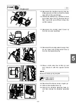
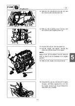
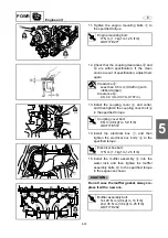
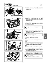
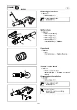
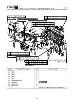
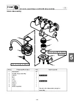
Electrical box and starter motor
Electrical box and starter motor removal
Step
Procedure/Part name
Q
’
ty
Service points
1
Ignition coil coupler
4
2
Plastic tie
1
3
Injector coupler
4
4
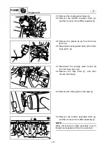
Knock sensor coupler
1
5
Thermoswitch coupler
1
6
Plastic tie
1
7
Cam position sensor coupler
1
8
Intake air temperature sensor
coupler
1
9
Engine temperature sensor coupler
1
10
Plastic tie
1
SG
SG
19
18
20
21
23
24
27
28
25
26
22
11
10
2
16
13
15
17
8
12
6
9
7
4
5
1
3
14
26
12
24
28
25
A
A
B
B
a
A
A
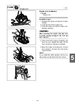
18 N
·
m (1.8 m
·
kg, 13.3 ft
·
Ib)
5 N
·
m (0.5 kgf
·
m, 3.7 ft
·
Ib)
8
×
30 mm
Summary of Contents for WaveRunner FX SHO
Page 1: ...SERVICE MANUAL FX SHO WaveRunner F1W 28197 1K 11 FX Cruiser SHO LIT 18616 03 12 LIT186160312 ...
Page 58: ...1 53 E GEN INFO MEMO Technical tips ...
Page 82: ...2 23 E SPEC MEMO Cable and hose routing ...
Page 110: ...3 27 E CHK ADJ MEMO General ...
Page 243: ...5 118 E POWR 1 2 3 4 5 6 7 8 9 MEMO Cooling water ...
Page 275: ...6 30 E JET PUMP 1 2 3 4 5 6 7 8 9 MEMO Intermediate housing ...
Page 353: ...E ELEC 1 2 3 4 5 6 7 8 9 7 76 MEMO Indication system ...
Page 410: ...8 55 E HULL HOOD MEMO Deck and hull ...
Page 429: ...9 18 E TRBL ANLS 1 2 3 4 5 6 7 8 9 MEMO Engine unit trouble analysis ...
Page 431: ......
Page 432: ...YAMAHA MOTOR CORPORATION USA Printed in USA Jan 2008 0 0 1 CR E ...


