


SPEC
9-26
CABLE ROUTING
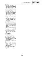
Tighten the ground lead
together with the flange bolt
above the rectifier/regulator
(point the terminal with the rivet
facing upward).
Pass the stator coil lead
between the rectifier/regulator
lead and the ground lead, and
then route it over the leads.
Fasten the wire harness and
stator coil lead with the holder.
Positive battery lead
Negative battery lead
Positive battery lead coupler
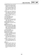
Fasten the wire harness and
stator coil lead with a plastic
band.
Negative battery lead coupler
Main fuse
Fasten the positive battery lead
and negative battery lead with
the holder.
Insert the projection on the wire
harness holder into the hole in
the frame cross member.
Route the stator coil lead under
the battery bracket.
Fasten the starter motor lead
and oil tank inlet hose with a
plastic band. Point the end of
the plastic band outward.
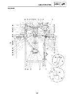
Pass the oil level switch lead to
front of the headlight stay.
Oil level switch
To parking brake
Fasten the wire harness to the
battery bracket with a plastic
band. Point the end of the plas-
tic band rearward.
Headlight couplers
Injector #3
ISC (idle speed control) unit
Fasten the wire harness to the
fuel rail with a plastic band.
Point the end of the plastic band
rearward.
0 – 10 mm (0 – 0.39 in)
Injector #2
Intake air pressure sensor 1
(cylinders #1, #2, and #3)
To speedometer unit
Intake air pressure sensor 2
(cylinder #1)
Injector #1
CABLE ROUTING
Summary of Contents for Vector RS90GTZ
Page 1: ......
Page 74: ...INSP ADJ 2 51 Rear RST90GTZ Nipple Nipple both sides LUBRICATION ...
Page 329: ...FI 7 2 Passenger grip warmer relay RS90GTZ RS90LTGTZ RST90GTZ FUEL INJECTION SYSTEM ...
Page 330: ...FI 7 3 CIRCUIT DIAGRAM RS90GTZ RS90LTGTZ FUEL INJECTION SYSTEM ...
Page 332: ...FI 7 5 CIRCUIT DIAGRAM RST90GTZ FUEL INJECTION SYSTEM ...
Page 368: ...ELEC 8 2 IGNITION SYSTEM CIRCUIT DIAGRAM RS90GTZ RS90LTGTZ IGNITION SYSTEM ...
Page 370: ...ELEC 8 4 CIRCUIT DIAGRAM RST90GTZ IGNITION SYSTEM ...
Page 393: ...ELEC 8 27 CHARGING SYSTEM ...
Page 394: ...ELEC 8 28 LIGHTING SYSTEM CIRCUIT DIAGRAM RS90GTZ RS90LTGTZ LIGHTING SYSTEM ...
Page 396: ...ELEC 8 30 CIRCUIT DIAGRAM RST90GTZ LIGHTING SYSTEM ...
Page 404: ...ELEC 8 38 SIGNAL SYSTEM CIRCUIT DIAGRAM RS90GTZ RS90LTGTZ SIGNAL SYSTEM ...
Page 406: ...ELEC 8 40 CIRCUIT DIAGRAM RST90GTZ SIGNAL SYSTEM ...
Page 419: ...ELEC 8 53 SIGNAL SYSTEM ...
Page 420: ...ELEC 8 54 GRIP WARMER SYSTEM CIRCUIT DIAGRAM RS90GTZ RS90LTGTZ GRIP WARMER SYSTEM ...
Page 422: ...ELEC 8 56 CIRCUIT DIAGRAM RST90GTZ GRIP WARMER SYSTEM ...
Page 430: ...ELEC 8 64 COOLING SYSTEM CIRCUIT DIAGRAM RS90GTZ RS90LTGTZ COOLING SYSTEM ...
Page 458: ...SPEC 9 25 CABLE ROUTING CABLE ROUTING ...
Page 460: ...SPEC 9 27 CABLE ROUTING ...
Page 462: ...SPEC 9 29 RS90GTZ RS90LTGTZ CABLE ROUTING ...
Page 464: ...SPEC 9 31 RS90GTZ RS90LTGTZ CABLE ROUTING ...
Page 466: ...SPEC 9 33 RST90GTZ CABLE ROUTING ...
Page 468: ...SPEC 9 35 RST90GTZ CABLE ROUTING ...
Page 470: ...SPEC 9 37 RST90GTZ CABLE ROUTING ...
Page 472: ...SPEC 9 39 RS90GTZ RS90LTGTZ CABLE ROUTING ...
Page 474: ...SPEC 9 41 RS90GTZ RS90LTGTZ CABLE ROUTING ...
Page 476: ...SPEC 9 43 RST90GTZ CABLE ROUTING ...
Page 478: ...SPEC 9 45 RST90GTZ CABLE ROUTING ...
Page 480: ...SPEC 9 47 CABLE ROUTING ...
Page 482: ...SPEC 9 49 CABLE ROUTING ...
Page 484: ...SPEC 9 51 RS90GTZ RS90LTGTZ CABLE ROUTING ...
Page 486: ...SPEC 9 53 RST90GTZ CABLE ROUTING ...
Page 488: ...SPEC 9 55 RS90GTZ RS90LTGTZ CABLE ROUTING ...
Page 490: ...SPEC 9 57 RST90GTZ CABLE ROUTING ...
Page 492: ...SPEC 9 59 RST90GTZ CABLE ROUTING ...
Page 498: ......
Page 499: ......
Page 500: ......
Page 501: ...WIRING DIAGRAM 2010 RS90GTZ RS90LTGTZ 8JA 0F001 00 ...
Page 502: ...WIRING DIAGRAM 2010 RST90GTZ 8HF 0F001 00 ...
Page 503: ...WIRING DIAGRAM 2010 RS90GTZ RS90LTGTZ 8JA 0F001 00 ...