background image

Instrument an

d

 control functions

3-20

3

EAU1234M

Han

d

le

b

ar switches

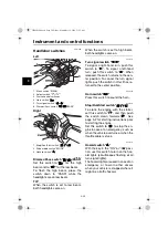
Left 

Ri

g

ht 

EAUM4031

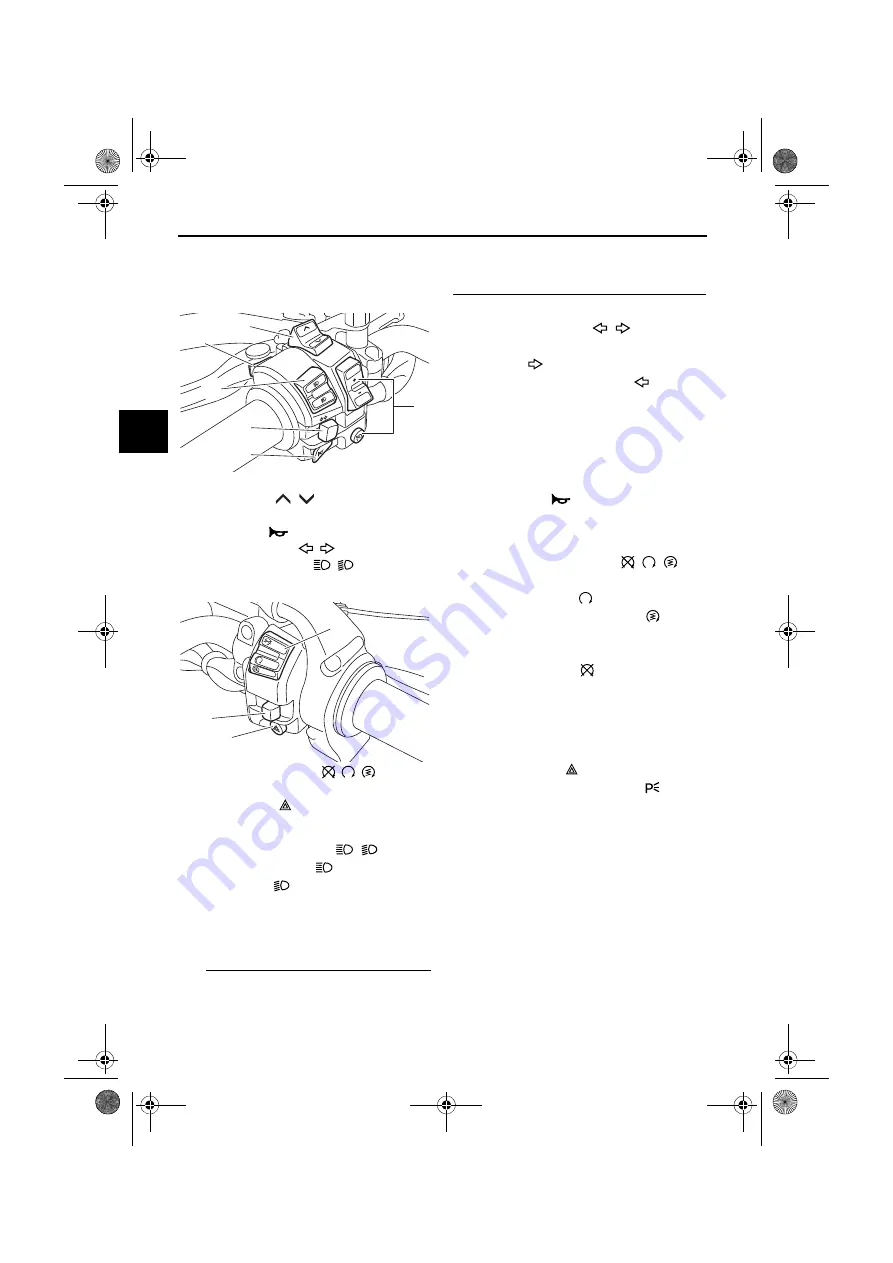
Dimmer/Pass switch “

/

/PASS”

Set this switch to “

” for the high

beam and to “

” for the low beam.

To flash the high beam, press the
switch down to “PASS” while the
headlights are on low beam.

TIP

When the switch is set to low beam,
both headlights come on.

When the switch is set to high beam,
both headlights come on.

EAU12461

Turn si

g

nal switch “

/

To signal a right-hand turn, push this
switch to “

”. To signal a left-hand

turn, push this switch to “

”. When

released, the switch returns to the cen-
ter position. To cancel the turn signal
lights, push the switch in after it has re-
turned to the center position.

EAU12501

Horn switch “

Press this switch to sound the horn.

EAU54212

Stop/Run/Start switch “

/

/

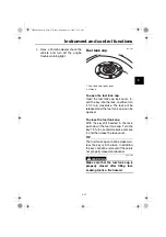
To crank the engine with the starter,
set this switch to “

”, and then push

the switch down towards “

”. See

page 5-2 for starting instructions prior
to starting the engine.
Set this switch to “

” to stop the en-

gine in case of an emergency, such as
when the vehicle overturns or when the
throttle cable is stuck.

EAU12735

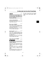
Hazar

d

 switch “

” 

With the key in the “ON” or “

” posi-

tion, use this switch to turn on the haz-
ard lights (simultaneous flashing of all
turn signal lights).
The hazard lights are used in case of an
emergency or to warn other drivers
when your vehicle is stopped where it
might be a traffic hazard.

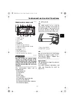
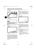
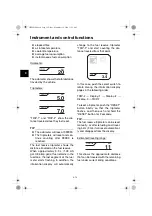
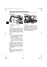
1. Menu switch “MENU”
2. Select switch “

/

3. Cruise control switches
4. Horn switch “

5. Turn signal switch “

/

6. Dimmer/Pass switch “

/

/PASS”

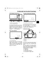
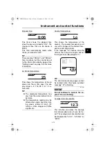
1. Stop/Run/Start switch “

/

/

2. Drive mode switch “MODE”
3. Hazard switch “

RE

S

SE

T

PA

SS

1

6

5

4

2

3

MODE

STOP

RUN

STA

RT

3

2

1

UBP8E1E0.book  Page 20  Friday, September 14, 2018  11:35 AM

Summary of Contents for Super Tenere ABS XT1200Z 2019

Page 1: ...DIC183 XT1200Z XT1200Z Super Ténéré ABS OWNER S MANUAL BP8 28199 E1 MOTORCYCLE English E Read this manual carefully before oper ating this vehicle ...

Page 2: ...ive 2014 53 EU The full text of the EU declaration of conformity is available at the following inter net address https global yamaha motor com eu_doc Frequency band 134 2 kHz The maximum radio frequency power 49 0 dBμV m Manufacturer YAMAHA MOTOR ELECTRONICS Co Ltd 1450 6 Mori Mori machi Shuchi Gun Shizuoka 437 0292 Japan Importer YAMAHA MOTOR EUROPE N V Koolhovenlaan 101 1119 NC Schiphol Rijk 111...

Page 3: ...n addition the many tips given in this manual will help keep your motorcycle in the best possible condition If you have any further questions do not hesitate to contact your Yamaha dealer The Yamaha team wishes you many safe and pleasant rides So remember to put safety first Yamaha continually seeks advancements in product design and quality There fore while this manual contains the most current p...

Page 4: ...th A WARNING indicates a hazardous situation which if not avoided could result in death or serious injury A NOTICE indicates special precautions that must be taken to avoid damage to the vehi cle or other property A TIP provides key information to make proce dures easier or clearer XT1200Z OWNER S MANUAL 2019 by Yamaha Motor Co Ltd 1st edition August 2018 All rights reserved Any reprinting or unau...

Page 5: ...Starting the engine 5 2 Shifting 5 3 Tips for reducing fuel consumption 5 4 Engine break in 5 5 Parking 5 6 Periodic maintenance and adjustment 6 1 Tool kit 6 2 Periodic maintenance charts 6 3 Periodic maintenance chart for the emission control system 6 3 General maintenance and lubrication chart 6 4 Removing and installing cowlings 6 7 Checking the spark plugs 6 9 Canister 6 10 Engine oil 6 10 Wh...

Page 6: ...t bulb 6 35 Turn signal light and brake tail light 6 37 Replacing a license plate light bulb 6 38 Supporting the motorcycle 6 39 Troubleshooting 6 39 Troubleshooting charts 6 40 Motorcycle care and storage 7 1 Matte color caution 7 1 Care 7 1 Storage 7 4 Specifications 8 1 Consumer information 9 1 Identification numbers 9 1 Diagnostic connector 9 2 Vehicle data recording 9 3 Index 10 1 UBP8E1E0 bo...

Page 7: ... Safe Riding Perform the pre operation checks each time you use the vehicle to make sure it is in safe operating condition Failure to inspect or maintain the vehi cle properly increases the possibility of an accident or equipment damage See page 4 1 for a list of pre operation checks This motorcycle is designed to carry the operator and a passen ger The failure of motorists to detect and recognize...

Page 8: ...e operator foot rests during operation to main tain control of the motorcycle The passenger should always hold onto the operator the seat strap or grab bar if equipped with both hands and keep both feet on the passenger footrests Never carry a passenger unless he or she can firmly place both feet on the passenger footrests Never ride under the influence of alcohol or other drugs Protective Apparel...

Page 9: ... of the motorcycle is changed To avoid the possibility of an accident use extreme caution when adding cargo or accessories to your motorcycle Use extra care when riding a motorcycle that has added cargo or accessories Here along with the information about accessories below are some general guidelines to follow if loading cargo to your motorcycle The total weight of the operator pas senger accessor...

Page 10: ...vehicle that change any of the vehicle s design or operation characteristics can put you and others at greater risk of serious injury or death You are responsible for injuries related to changes in the vehicle Keep the following guidelines in mind as well as those provided under Load ing when mounting accessories Never install accessories or carry cargo that would impair the per formance of your m...

Page 11: ...truc tions before transporting the motorcy cle in another vehicle Remove all loose items from the motorcycle Check that the fuel cock if equipped is in the OFF position and that there are no fuel leaks Point the front wheel straight ahead on the trailer or in the truck bed and choke it in a rail to pre vent movement Shift the transmission in gear for models with a manual transmis sion Secure the m...

Page 12: ... 3 30 5 Carrier page 3 37 6 Final gear oil filler bolt page 6 14 7 Final gear oil drain bolt page 6 14 8 Coolant reservoir page 6 16 9 Shift pedal page 3 22 10 Engine oil drain bolt oil tank page 6 10 11 Engine oil drain bolt crankcase page 6 10 12 Engine oil filter cartridge page 6 10 13 Compression damping force adjuster page 3 34 UBP8E1E0 book Page 1 Friday September 14 2018 11 35 AM ...

Page 13: ...25 2 Spring preload adjuster page 3 36 3 Fuses page 6 32 4 Tool kit page 6 2 5 Battery page 6 30 6 Engine oil filler cap page 6 10 7 Engine oil level check window page 6 10 8 Brake pedal page 3 24 9 Rebound damping force adjuster page 3 36 UBP8E1E0 book Page 2 Friday September 14 2018 11 35 AM ...

Page 14: ...e 3 20 3 Clutch fluid reservoir page 6 25 4 Multi function meter unit page 3 9 5 Auxiliary DC jack page 3 39 6 Front brake fluid reservoir page 6 25 7 Right handlebar switches page 3 20 8 Brake lever page 3 23 9 Throttle grip page 6 18 10 Main switch steering lock page 3 2 UBP8E1E0 book Page 3 Friday September 14 2018 11 35 AM ...

Page 15: ...Keep the standard keys as well as keys of other immobilizer systems away from the code re registering key Keep other immobilizer system keys away from the main switch as they may cause signal interfer ence NOTICE ECA11823 DO NOT LOSE THE CODE RE REG ISTERING KEY CONTACT YOUR DEALER IMMEDIATELY IF IT IS LOST If the code re registering key is lost the existing standard keys can still be used to star...

Page 16: ... leave the key in the on position without the engine running The headlight comes on automat ically when the engine is started EAU10662 OFF All electrical systems are off The key can be removed WARNING EWA10062 Never turn the key to OFF or LOCK while the vehicle is moving Otherwise the electrical systems will be switched off which may result in loss of control or an accident EAU10696 LOCK The steer...

Page 17: ...its corresponding turn signal lights are flashing EAU11061 Neutral indicator light This indicator light comes on when the transmission is in the neutral position EAU11081 High beam indicator light This indicator light comes on when the high beam of the headlight is switched on 1 Push 2 Turn 1 2 1 Left turn signal indicator light 2 Right turn signal indicator light 3 Oil level warning light 4 Engin...

Page 18: ...come on have a Yamaha dealer check the vehicle EAU73172 Engine trouble warning light This warning light comes on if a prob lem is detected in the engine or other vehicle control system If this occurs have a Yamaha dealer check the on board diagnostic system TIP When the vehicle is turned on the light will come on for a few seconds and then go off If the light does not come on or if the light remai...

Page 19: ...key to ON The indicator light should come on for a few seconds and then go off If the indicator light does not come on initially when the key is turned to ON if the indicator light remains on or if the indicator light flashes in a pattern if a problem is detected in the immobilizer system the immobilizer system indica tor light will flash in a pattern have a Yamaha dealer check the vehicle TIP If ...

Page 20: ...ather conditions or among winding slippery hilly rough or gravel roads When traveling uphill or down hill the cruise control system may not be able to maintain the set cruising speed To prevent accidentally activat ing the cruise control system turn it off when not in use Make sure that the cruise control sys tem indicator light is off Activating and setting the cruise control system 1 Push the cr...

Page 21: ...f the setting switch If you do not set a new cruising speed when you return the throttle grip the vehicle will decelerate to the previously set cruising speed Deactivating the cruise control sys tem Perform one of the following opera tions to cancel the set cruising speed The SET indicator light will go off Turn the throttle grip past the closed position in the deceleration direction Apply the fro...

Page 22: ...bove condi tions the indicator light will go off and the SET indicator light will flash for 4 seconds and then go off When not traveling with a set cruising speed if the start engine stop switch is set to the position the engine stalls or the sidestand is lowered then the indicator light will go off the SET indicator light will not flash If the cruise control system is automat ically deactivated p...

Page 23: ...ndlebar These switches al low you to control or change the set tings of the multi function meter unit TIP Be sure to turn the key to ON before pushing the select switch menu switch MENU RESET but ton and TCS button Speedometer The speedometer shows the vehicle s traveling speed To switch between kilometers and miles see Selecting the units on page 3 16 1 RESET button 2 TCS button 3 Clock 4 Tachome...

Page 24: ...m is detected in the fuel me ter circuit all display segments of the fuel meter will start flashing If this oc curs have a Yamaha dealer check the vehicle Eco indicator This indicator comes on when the vehi cle is being operated in an environ mentally friendly fuel efficient manner The indicator goes off when the vehicle is stopped TIP Consider the following tips to reduce fuel consumption Avoid h...

Page 25: ...ol system see page 3 25 Information display There are 3 information display pages Push the select switch rotate between them You can select and arrange which items will be shown on each informa tion display page See page 3 17 The following items are available odometer tripmeters fuel reserve tripmeter estimated traveling range 1 Neutral indicator light 2 Transmission gear indicator 1 Drive mode in...

Page 26: ...rmation display will automatically change to the fuel reserve tripmeter TRIP F and start counting the dis tance traveled from that point In this case push the select switch to rotate among the information display pages in the following order TRIP F Display 1 Display 2 Display 3 TRIP F To reset a tripmeter push the RESET button briefly so that the tripmeter flashes and then push and hold the RESET ...

Page 27: ...fected by engine heat when rid ing slowly under 20 km h 12 mi h or when stopped at traffic signals etc Coolant temperature This shows the temperature of the coolant The coolant temperature will vary with changes in the ambient tem perature and engine load If the message Hi flashes stop the vehicle then stop the engine and let the engine cool See page 6 41 TIP The information display pages cannot b...

Page 28: ...tantaneous fuel consumption can be displayed as km L L 100km or MPG km L shows the number of kilo meters traveled on one liter of fuel L 100km shows how many liters of fuel is needed to travel 100 km MPG shows the number of miles traveled per Imp gallon of fuel TIP See Selecting the units on page 3 16 to change the kilometer based fuel consumption units or to switch to miles When traveling under 1...

Page 29: ...EE 2 maintenance intervals Check and reset the TIME 2 and TIME 3 timers These timers show the total elapsed time that the key has been in the ON position When the key is turned to OFF these timers stop counting but are not reset The maximum time that can be shown is 99 59 When the time trips ex ceed 99 59 they will reset and continue counting Switch the multi function meter distance units be tween...

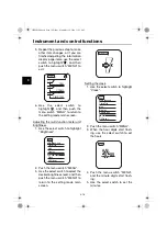
Page 30: ...highlight Unit 2 Push the menu switch MENU The unit setting display will be shown and km or mile will flash in the display 3 Push the menu switch MENU km or mile will flash in the dis play 4 Use the select switch to select km or mile and then push the menu switch MENU MENU Maintenance Time Trip Unit Display Brightness Clock All Reset TIME 2 0 07 TIME 3 0 07 Time Trip MENU Maintenance Time Trip Uni...

Page 31: ...on display page items 1 Use the select switch to highlight Display 2 Push the menu switch MENU use the select switch to highlight the page you want to adjust and then push the menu switch MENU again 3 Use the select switch to highlight the item you want to change and then push the menu switch MENU 4 Use the select switch to select the item that you want to appear and then push the menu switch MENU...

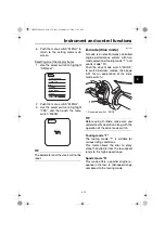
Page 32: ...MENU 3 Use the select switch to select the desired brightness level and then push the menu switch MENU to return to the setting mode main screen Setting the clock 1 Use the select switch to highlight Clock 2 Push the menu switch MENU 3 When the hour digits start flash ing use the select switch to set the hours 4 Push the menu switch MENU and the minute digits start flash ing 5 Use the select switc...

Page 33: ... drive mode switch MODE to switch between modes See page 3 21 for an explanation of the drive mode switch TIP Before using D mode make sure you understand its operation along with the operation of the drive mode switch Touring mode T The touring mode T is suitable for various riding conditions This mode allows the rider to enjoy smooth drivability from the low speed range to the high speed range S...

Page 34: ...orn EAU54212 Stop Run Start switch To crank the engine with the starter set this switch to and then push the switch down towards See page 5 2 for starting instructions prior to starting the engine Set this switch to to stop the en gine in case of an emergency such as when the vehicle overturns or when the throttle cable is stuck EAU12735 Hazard switch With the key in the ON or posi tion use this s...

Page 35: ...AU59001 Select switch This switch is used to perform selec tions in the information display and setting mode display of the multi func tion meter unit See Multi function meter unit on page 3 9 for detailed information EAU54691 Drive mode switch MODE WARNING EWA15341 Do not change the D mode while the vehicle is moving Using this switch changes the drive mode to touring mode T or sports mode S The ...

Page 36: ...on of the clutch lever can be adjusted To adjust the distance be tween the clutch lever and the handle bar gently push the lever away from the handlebar and rotate the position adjusting dial TIP Make sure the setting number on the position adjusting dial aligns with the match mark EAU12876 Shift pedal The shift pedal is located on the left side of the motorcycle To shift the transmission to a hig...

Page 37: ...oth the brake lever and the brake pedal simultaneously The unified brake system is monitored by an ECU which disables unified braking and resumes conventional braking if a malfunction occurs TIP UBS does not function until the vehicle starts moving However after coming to a stop while apply ing the brake lever UBS will re main engaged As UBS applies only a portion of the rear brake depress the bra...

Page 38: ...will re duce braking effectiveness WARNING EWA16051 Always keep a sufficient distance from the vehicle ahead to match the riding speed even with ABS The ABS performs best with long braking distances On certain surfaces such as rough or gravel roads the brak ing distance may be longer with the ABS than without The ABS is monitored by an ECU which will revert the system to conven tional braking if a...

Page 39: ...aces such as unpaved or wet roads If sensors detect that the rear wheel is starting to slip uncon trolled spinning the traction control system assists by regulating engine power as needed until traction is re stored WARNING EWA15433 The traction control system is not a substitute for riding appropriately for the conditions Traction control cannot prevent loss of traction due to excessive speed whe...

Page 40: ...anging settings while riding can distract the operator and increase the risk of an accident The traction control system mode can be changed only when the vehicle is stopped Push the TCS button to change between modes 1 and 2 Push the button for two seconds to select TCS OFF and turn the traction control system off Push the button again to return to the previously selected mode Resetting The tracti...

Page 41: ...To close the fuel tank cap With the key still inserted in the lock push down the fuel tank cap Turn the key 1 4 turn counterclockwise remove it and then close the lock cover TIP The fuel tank cap cannot be closed un less the key is in the lock In addition the key cannot be removed if the cap is not properly closed and locked WARNING EWA11092 Make sure that the fuel tank cap is properly closed afte...

Page 42: ...ed fuel immedi ately NOTICE Immediately wipe off spilled fuel with a clean dry soft cloth since fuel may deteriorate painted surfaces or plastic parts ECA10072 4 Be sure to securely close the fuel tank cap WARNING EWA15152 Gasoline is poisonous and can cause injury or death Handle gaso line with care Never siphon gasoline by mouth If you should swallow some gasoline or inhale a lot of gas oline va...

Page 43: ...on taining methanol Gasohol containing ethanol can be used if the ethanol con tent does not exceed 10 E10 Gas ohol containing methanol is not recommended by Yamaha because it can cause damage to the fuel system or vehicle performance problems EAU79161 Fuel tank overflow hose TIP See page 6 10 for breather hose infor mation Before operating the motorcycle Check the fuel tank overflow hose connectio...

Page 44: ...ne to idle more than a few minutes Long idling can cause a build up of heat NOTICE ECA10702 Use only unleaded gasoline The use of leaded gasoline will cause unre pairable damage to the catalytic converter EAU49445 Rider seat To remove the rider seat 1 Insert the key into the seat lock and then turn it counterclockwise 2 Lift the front of the rider seat and push the seat forward To install the ride...

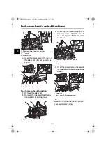
Page 45: ...s sembly the rider seat height is set to the high position To change to the low position 1 Remove the rider seat 2 Remove the rider seat height posi tion adjuster by pulling it out 3 Install the rider seat height posi tion adjuster so that the match mark is aligned with the L mark as shown 1 Low position 2 High position 1 Rider seat height position adjuster 1 2 1 UBP8E1E0 book Page 31 Friday Septe...

Page 46: ...rk is aligned with the H mark as shown 4 Insert the projection on the rear of the rider seat into seat holder B as shown TIP Make sure that the rider seat is proper ly secured before riding 1 Rider seat height position adjuster 2 L mark 3 Match mark 1 Projection 2 Seat holder A for low position 1 Rider seat height position adjuster 3 2 1 1 2 1 1 Rider seat height position adjuster 2 H mark 3 Match...

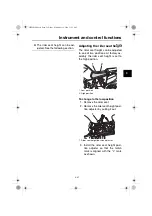
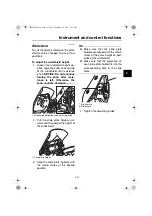
Page 47: ... ECA20211 2 Pull the slide plate holders out ward and then adjust the height of the windshield 3 Align the slide plate holders with the match marks at the desired position TIP Make sure that the slide plate holders are aligned with the match marks at the same height on both sides of the windshield Make sure that the projection on each slide plate holder fits into the corresponding hole in the slid...

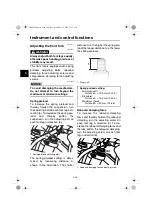
Page 48: ...ion turn the adjusting bolt on each fork leg in direction b The spring preload setting is deter mined by measuring distance A shown in the illustration The shorter distance A is the higher the spring pre load the longer distance A is the lower the spring preload Rebound damping force To increase the rebound damping force and thereby harden the rebound damping turn the adjusting screw on each fork ...

Page 49: ...ngs turn the adjuster in direc tion a until it stops and then count the clicks in direction b Although a damping force adjust er may click beyond the stated minimum settings such adjust ments are ineffective and may damage the suspension When turning a damping force ad juster in direction a the 0 click position and the 1 click position may be the same Rebound damping setting Minimum soft 10 click ...

Page 50: ...adjusting mechanism with the matching edge When adjusting the spring pre load there should be no weight on the rear of the vehicle Rebound damping force To increase the rebound damping force and thereby harden the rebound damping turn the adjusting knob in di rection a To decrease the rebound damping force and thereby soften the rebound damping turn the adjusting knob in direction b TIP When adjus...

Page 51: ...e to excessive gas pressure Do not deform or damage the cylinder in any way Cylinder damage will result in poor damping performance Do not dispose of a damaged or worn out shock absorber as sembly yourself Take the shock absorber assembly to a Yamaha dealer for any service EAU49705 Carriers This motorcycle is equipped with a standard carrier and with an additional carrier located under the passeng...

Page 52: ...Do not exceed the additional carrier capacity of 5 0 kg 11 lb NOTICE ECA16822 Do not lift the vehicle by either carri er EAU84680 Luggage strap holders Use the indicated strap points to se cure luggage ties to the vehicle 1 Luggage strap holder 1 UBP8E1E0 book Page 38 Friday September 14 2018 11 35 AM ...

Page 53: ...low or the battery may discharge To use the auxiliary DC jack 1 Turn the main switch off 2 Remove the auxiliary DC jack cap 3 Turn the accessory off 4 Insert the accessory plug into the auxiliary DC jack 5 Turn the main switch on and start the engine See page 5 2 6 Turn the accessory on WARNING EWA14361 To prevent electrical shock or short circuiting make sure that the cap is installed when the au...

Page 54: ...ct the operator resulting in a possible loss of control Yamaha s ignition circuit cut off system has been designed to assist the operator in fulfilling the respon sibility of raising the sidestand be fore starting off Therefore check this system regularly and have a Yamaha dealer repair it if it does not function properly EAU83150 Ignition circuit cut off system This system prevents in gear engine...

Page 55: ...s stalled 10 Move the sidestand up 11 Pull the clutch lever 12 Push the start switch Does the engine start The system is OK The motorcycle can be ridden The neutral switch may not be working The motorcycle should not be ridden until checked by a Yamaha dealer The sidestand switch may not be working The motorcycle should not be ridden until checked by a Yamaha dealer The clutch switch may not be wo...

Page 56: ...oil Check oil level in engine If necessary add recommended oil to specified level Check vehicle for oil leakage 6 10 Final gear oil Check vehicle for oil leakage 6 14 Coolant Check coolant level in reservoir If necessary add recommended coolant to specified level Check cooling system for leakage 6 16 Front brake Check operation If soft or spongy have Yamaha dealer bleed hydraulic system Check brak...

Page 57: ... pedal pivoting points if necessary 6 27 Brake and clutch le vers Make sure that operation is smooth Lubricate lever pivoting points if necessary 6 27 Sidestand Make sure that operation is smooth Lubricate pivot if necessary 6 28 Chassis fasteners Make sure that all nuts bolts and screws are properly tightened Tighten if necessary Instruments lights signals and switches Check operation Correct if ...

Page 58: ... accident or injury EAU73451 TIP This model is equipped with a lean angle sensor to stop the en gine in case of turnover Turn the main switch off once before at tempting to restart the engine Failing to do so will prevent the en gine from starting even though the engine will crank when the start switch is pushed an engine auto stop system The engine stops automatically if left idling for 20 minute...

Page 59: ...icator light ABS warning light Neutral indicator light TIP The ABS warning light should go off when the vehicle reaches a traveling speed of 10 km h 6 mi h The neutral indicator light should be on when the transmission is in neutral NOTICE ECA24110 If a warning or indicator light does not work as described above have a Yamaha dealer check the vehicle 3 Shift the transmission into neutral 4 Push th...

Page 60: ...ccelerate 1 Pull the clutch lever to disengage the clutch 2 Shift the transmission into first gear The neutral indicator light should go out 3 Open the throttle gradually and at the same time release the clutch lever slowly 4 After starting out close the throt tle and at the same time quickly pull the clutch lever in 5 Shift the transmission into second gear Make sure not to shift the transmission...

Page 61: ...tion or the engine to over rev This could cause loss of control an accident and injury It could also cause engine or drive train dam age EAU16811 Tips for reducing fuel con sumption Fuel consumption depends largely on your riding style Consider the follow ing tips to reduce fuel consumption Shift up swiftly and avoid high en gine speeds during acceleration Do not rev the engine while shift ing dow...

Page 62: ...tion or any condition that might result in engine overheating must be avoided EAU58991 0 1000 km 0 600 mi Avoid prolonged operation above 3900 r min NOTICE After 1000 km 600 mi of operation the engine oil and final gear oil must be changed and the oil filter cartridge or element re placed ECA10333 1000 1600 km 600 1000 mi Avoid prolonged operation above 4700 r min 1600 km 1000 mi and beyond The ve...

Page 63: ...exhaust system can become very hot park in a place where pedestri ans or children are not likely to touch them and be burned Do not park on a slope or on soft ground otherwise the vehicle may overturn increasing the risk of a fuel leak and fire Do not park near grass or other flammable materials which might catch fire UBP8E1E0 book Page 6 Friday September 14 2018 11 35 AM ...

Page 64: ...ntain the vehi cle or performing maintenance ac tivities incorrectly may increase your risk of injury or death during service or while using the vehicle If you are not familiar with vehicle ser vice have a Yamaha dealer perform service WARNING EWA15123 Turn off the engine when performing maintenance unless otherwise specified A running engine has moving parts that can catch on body parts or clothi...

Page 65: ...tablishment or individual that is certified if applicable Yamaha dealers are trained and equipped to perform these particular services EAU85230 Tool kit The tool kit is in the location shown The information included in this manual and the tools provided in the tool kit are intended to assist you in the perfor mance of preventive maintenance and minor repairs However a torque wrench and other tools...

Page 66: ...chart for the emission control system NO ITEM 1 Fuel line Check fuel hoses for cracks or damage Replace if necessary 2 Spark plugs Check condition Adjust gap and clean Replace 3 Valve clearance Check and adjust Every 40000 km 24000 mi 4 Fuel injection Check engine idle speed Check and adjust synchroniza tion 5 Exhaust system Check for leakage Tighten if necessary Replace gaskets if necessary 6 Eva...

Page 67: ...e Replace Every 4 years 7 Brake fluid Change Every 2 years 8 Wheels Check runout and for damage Tighten all spokes At the initial interval and every 5000 km 3000 mi thereafter 9 Tires Check tread depth and for damage Replace if necessary Check air pressure Correct if necessary 10 Wheel bearings Check bearing for looseness or damage 11 Swingarm pivot bearings Check operation and for exces sive play...

Page 68: ...h Check operation and replace if necessary 20 Front fork Check operation and for oil leakage Replace if necessary 21 Shock absorber assembly Check operation and for oil leakage Replace if necessary 22 Rear suspension relay arm and con necting arm pivot ing points Check operation 23 Engine oil Change warm engine before draining Check oil level and vehicle for oil leakage 24 Engine oil filter cartri...

Page 69: ...lipers as well as clutch master and release cylinders and change the brake and clutch fluids Replace the brake and clutch hoses every four years or sooner if cracked or damaged 26 Final gear oil Check oil level and vehicle for oil leakage Change 27 Front and rear brake switches Check operation 28 Moving parts and cables Lubricate 29 Throttle grip hous ing and cable Check operation and free play Ad...

Page 70: ...move the quick fastener screws and then pull the cowling off as shown To install the cowling 1 Fit the projections on the cowling into the matching holes in cowling B 2 Install the quick fastener screws Cowling B To remove the cowling 1 Remove cowling A 2 Remove the bolts and the quick fasteners and then pull the cowl ing off 1 Cowling A 2 Cowling B 1 Cowling C 1 2 1 1 Cowling A 2 Quick fastener s...

Page 71: ...l cowling A Cowling C To remove the cowling Remove the bolts and the nuts and then take the cowling off To install the cowling Place the cowling in the original posi tion and then install the bolts and the nuts 1 Cowling B 2 Bolt 1 Quick fastener 2 1 2 1 1 Cowling C 2 Nut 3 Bolt 1 Cowling C 2 Nut 3 Bolt 2 3 1 1 2 3 UBP8E1E0 book Page 8 Friday September 14 2018 11 35 AM ...

Page 72: ...xcessive carbon or other deposits it should be replaced Before installing a spark plug the spark plug gap should be measured with a wire thickness gauge and if necessary adjusted to specification Clean the surface of the spark plug gasket and its mating surface and then wipe off any grime from the spark plug threads TIP If a torque wrench is not available when installing a spark plug a good estima...

Page 73: ...event clutch slip page since the engine oil also lubricates the clutch do not mix any chemical additives Do not use oils with a diesel speci fication of CD or oils of a high er quality than specified In addition do not use oils labeled ENERGY CONSERVING II or higher Make sure that no foreign mate rial enters the crankcase To check the engine oil level 1 With the vehicle on a level surface hold it ...

Page 74: ...p the oil and then stop the engine 2 Place an oil pan under the oil tank to collect the used oil 3 Remove the engine oil filler cap the drain bolt and its gasket to drain the oil from the oil tank 4 Place an oil pan under the engine to collect the used oil 5 Remove the engine oil drain bolt and its gasket to drain the oil from the crankcase TIP Skip steps 6 10 if the oil filter cartridge is not be...

Page 75: ...the specified torques 12 Refill with the specified amount of the recommended engine oil TIP Using a funnel is recommended 13 After checking the engine oil filler cap O ring install the filler cap TIP Wipe off any spilled oil before starting the engine 14 Start the engine and let it idle while checking for oil leaks TIP If any oil leaks are found which you cannot fix have the vehicle inspected 1 Oi...

Page 76: ...ists in the fields of me chanical engineering chemistry elec tronics and track testing and have them develop the engine together with the oil it will use Yamalube oils take full advantage of the base oil s qualities and blend in the ideal balance of addi tives to make sure the final oil clears our performance standards Thus Yamalube mineral semisynthetic and synthetic oils have their own distinct ...

Page 77: ...o the side can re sult in a false reading 2 Remove the final gear oil filler bolt and its gasket and then check the oil level in the final gear case TIP The oil level should be at the brim of the filler hole 3 If the oil is below the brim of the filler hole add sufficient oil of the recommended type to raise it to the correct level 4 Check the gasket for damage and replace it if necessary 5 Instal...

Page 78: ...hen tighten the bolt to the specified torque 7 Check the final gear case for oil leakage If oil is leaking check for the cause 1 Final gear oil filler bolt 2 Final gear oil drain bolt 3 Gasket Tightening torque Final gear oil drain bolt 23 N m 2 3 kgf m 17 lb ft Recommended final gear oil Yamaha genuine shaft drive gear oil SAE 80W 90 API GL 5 or SAE 80 API GL 4 Hypoid gear oil Oil quantity 0 20 L...

Page 79: ...coolant to the maximum level mark NOTICE If coolant is not available use distilled water or soft tap water instead Do not use hard water or salt water since it is harmful to the engine If water has been used instead of coolant replace it with cool ant as soon as possible other wise the cooling system will not be protected against frost and corrosion If water has been added to the coolant have a Ya...

Page 80: ...ove the radiator cap when the engine is hot EWA10382 EAU36765 Air filter element The air filter element must be replaced at the intervals specified in the periodic maintenance and lubrication chart Have a Yamaha dealer replace the air filter element UBP8E1E0 book Page 17 Friday September 14 2018 11 35 AM ...

Page 81: ...a dealer EAU21386 Checking the throttle grip free play Measure the throttle grip free play as shown Periodically check the throttle grip free play and if necessary have a Yamaha dealer adjust it Engine idling speed 1050 1150 r min 1 Throttle grip free play Throttle grip free play 3 0 5 0 mm 0 12 0 20 in 1 UBP8E1E0 book Page 18 Friday September 14 2018 11 35 AM ...

Page 82: ... all con ditions of riding depends on a relatively small area of road contact Therefore it is essential to maintain the tires in good condition at all times and replace them at the appropriate time with the speci fied tires Tire air pressure The tire air pressure should be checked and if necessary adjusted before each ride WARNING EWA10504 Operation of this vehicle with im proper tire pressure may...

Page 83: ...ead to loss of control The replacement of all wheel and brake related parts includ ing the tires should be left to a Yamaha dealer who has the necessary professional knowl edge and experience to do so Ride at moderate speeds after changing a tire since the tire surface must first be broken in for it to develop its optimal characteristics Tire information Cold tire air pressure 1 person Front 225 k...

Page 84: ...extensive tests only the tires list ed below have been approved for this model by Yamaha WARNING EWA10601 This motorcycle is fitted with super high speed tires Note the following points in order to make the most ef ficient use of these tires Use only the specified replace ment tires Other tires may run the danger of bursting at super high speeds Brand new tires can have a rel atively poor grip on ...

Page 85: ...ignment Have the wheel balanced whenev er the tire or tube has been re placed An unbalanced wheel can result in adverse handling charac teristics and shortened tire life EAU42851 Clutch lever Since this model is equipped with a hy draulic clutch adjusting the clutch le ver free play is not needed However it is necessary to check the hydraulic system for leakage before each ride If the clutch lever...

Page 86: ... Yamaha dealer bleed the system be fore operating the vehicle Air in the hydraulic system will diminish the braking performance which may re sult in loss of control and an acci dent EAU36505 Brake light switches The brake light should come on just before braking takes effect The brake light is activated by switches connect ed to the brake lever and brake pedal Since the brake light switches are co...

Page 87: ...e brake To check the brake pad wear check the position of the wear indicators while applying the brake If a brake pad has worn to the point that a wear indicator almost touches the brake disc have a Yamaha dealer replace the brake pads as a set EAU22501 Rear brake pads Check each rear brake pad for damage and measure the lining thickness If a brake pad is damaged or if the lining thickness is less...

Page 88: ...a brake fluid other than DOT 4 may result in a harmful chemical reaction Be careful that water or dust does not enter the brake fluid reservoir when refilling Water will significantly lower the boil ing point of the fluid and may re sult in vapor lock and dirt may clog the ABS hydraulic unit valves NOTICE ECA17641 Brake fluid may damage painted surfaces or plastic parts Always clean up spilled flu...

Page 89: ...every four years EAU23115 Checking and lubricating the throttle grip and cable The operation of the throttle grip should be checked before each ride In addition the cable should be lubricat ed by a Yamaha dealer at the intervals specified in the periodic maintenance chart The throttle cable is equipped with a rubber cover Make sure that the cover is securely installed Even though the cover is inst...

Page 90: ... lu bricated if necessary Brake pedal Shift pedal EAU43602 Checking and lubricating the brake and clutch levers The operation of the brake and clutch levers should be checked before each ride and the lever pivots should be lu bricated if necessary Brake lever Clutch lever Recommended lubricant Lithium soap based grease Recommended lubricant Silicone grease UBP8E1E0 book Page 27 Friday September 14...

Page 91: ...and down smoothly have a Yamaha dealer check or repair it Otherwise the sidestand could contact the ground and distract the operator re sulting in a possible loss of control EAUM1653 Lubricating the swingarm piv ots The swingarm pivots must be lubricat ed by a Yamaha dealer at the intervals specified in the periodic maintenance and lubrication chart Recommended lubricant Lithium soap based grease ...

Page 92: ...times to check if the front fork compresses and re bounds smoothly NOTICE ECA10591 If any damage is found or the front fork does not operate smoothly have a Yamaha dealer check or re pair it EAU23285 Checking the steering Worn or loose steering bearings may cause danger Therefore the operation of the steering must be checked as fol lows at the intervals specified in the periodic maintenance and lu...

Page 93: ...yte or to add distilled water However the battery lead connections need to be checked and if necessary tight ened WARNING EWA10761 Electrolyte is poisonous and dangerous since it contains sul furic acid which causes severe burns Avoid any contact with skin eyes or clothing and al ways shield your eyes when working near batteries In case of contact administer the fol lowing FIRST AID EXTERNAL Flush...

Page 94: ...e battery To store the battery 1 If the vehicle will not be used for more than one month remove the battery fully charge it and then place it in a cool dry place NOTICE When removing the battery be sure to turn the main switch off then disconnect the negative lead before discon necting the positive lead ECA16304 2 If the battery will be stored for more than two months check it at least once a mont...

Page 95: ...amperage rating than recommended to avoid causing extensive dam age to the electrical system and possibly a fire EWA15132 1 ABS motor fuse 2 ABS motor spare fuse 3 Main fuse 4 Spare fuse 5 Cruise control fuse 6 Brake light fuse 7 Fuse box 1 2 3 5 4 6 7 1 Headlight fuse 2 ABS solenoid fuse 3 Electronic throttle valve fuse 4 Fuel injection system fuse 5 Backup fuse for clock and immobilizer sys tem ...

Page 96: ...hly clean off any dirt and fin gerprints on the headlight bulb using a cloth moistened with al cohol or thinner Headlight lens Do not affix any type of tinted film or stickers to the headlight lens Do not use a headlight bulb of a wattage higher than specified 1 Remove the headlight bulb cover by turning it counterclockwise Specified fuses Main fuse 50 0 A Terminal fuse 1 3 0 A Headlight fuse 20 0...

Page 97: ...dlight bulb into position and then secure it with the bulb holder 5 Connect the headlight coupler 6 Install the headlight bulb cover by turning it clockwise 7 Have a Yamaha dealer adjust the headlight beam if necessary 1 Headlight bulb cover 1 Headlight coupler 1 Headlight bulb 2 Headlight bulb holder 1 1 1 2 UBP8E1E0 book Page 34 Friday September 14 2018 11 35 AM ...

Page 98: ...ward 3 Remove the panel by removing the screws and the quick fastener screw 4 Remove the headlight unit cover by removing the bolts 5 Remove the headlight unit bolts then pull the headlight unit slightly out making sure that it remains supported NOTICE Be careful not to pull the headlight leads ECA16811 1 Windshield 2 Screw 1 Cover 1 2 2 1 1 Panel 2 Screw 3 Quick fastener screw 1 Headlight unit co...

Page 99: ...and then tightening them to the specified torque 11 Install the headlight unit cover by installing the bolts 12 Install the panel by installing the screws and the quick fastener screw 13 Install the cover 14 Install the windshield by installing the screws and then tightening them to the specified torque WARNING A loose windshield 1 Headlight unit 2 Headlight unit bolt 1 Headlight lead 1 Auxiliary ...

Page 100: ...urn signal light and brake tail light This model is equipped with LED type turn signal lights and an LED type brake tail light If a turn signal light or the brake tail light does not come on have a Yamaha dealer check it Tightening torque Windshield screw 0 5 N m 0 05 kgf m 0 37 lb ft UBP8E1E0 book Page 37 Friday September 14 2018 11 35 AM ...

Page 101: ... Remove the burnt out bulb by pulling it out 4 Insert a new bulb into the socket 5 Install the socket together with the bulb by pushing it in and then turning it clockwise until it stops 6 Place the license plate light unit in the original position and then in stall the bolts 1 License plate light unit 2 License plate light unit bolt 1 License plate light bulb socket 2 1 1 1 License plate light bu...

Page 102: ... rear wheel or under each side of the swingarm EAU25872 Troubleshooting Although Yamaha motorcycles receive a thorough inspection before shipment from the factory trouble may occur during operation Any problem in the fuel compression or ignition systems for example can cause poor starting and loss of power The following troubleshooting charts represent quick and easy procedures for checking these ...

Page 103: ...ave a Yamaha dealer charge the battery if necessary 2 Battery The battery is good The engine does not start Check the ignition 3 Ignition Wet Operate the electric starter Dry There is compression There is no compression The engine does not start Have a Yamaha dealer check the vehicle Have a Yamaha dealer check the vehicle The engine does not start Check the compression Have a Yamaha dealer check t...

Page 104: ...d press down on the cap while turning it counterclockwise and then remove the cap TIP If coolant is not available tap water can be temporarily used instead provided that it is changed to the recommended coolant as soon as possible Wait until the engine has cooled Check the coolant level in the reservoir and radiator Add coolant See TIP The coolant level is OK There is no leakage There is leakage T...

Page 105: ...le more frequently Be sure to wash the vehicle after riding in the rain or near the sea because salt is corro sive to metals TIP The roads of heavy snowfall areas may be sprayed with salt as a de icing method This salt can stay on the roads well into spring so be sure to wash the underside and chassis parts after riding in such areas Genuine Yamaha care and main tenance products are sold under the...

Page 106: ...1 Rinse off any degreaser and spray down the vehicle with a garden hose Use only enough pressure to do the job Avoid spraying wa ter directly into the muffler instru ment panel air inlet or other inner areas such as underseat storage compartments 2 Wash the vehicle with a quality au tomotive type detergent mixed with cool water and a soft clean towel or sponge Use an old tooth brush or plastic bri...

Page 107: ...painted surfaces using a non abrasive wax or use a detail spray for motorcycles 8 When finished cleaning start the engine and let it idle for several minutes to help dry any remaining moisture 9 If the headlight lens has fogged up start the engine and turn on the headlight to help remove the moisture 10 Let the vehicle dry completely be fore storing or covering it NOTICE ECA26320 Do not apply wax ...

Page 108: ...l cock Turn the fuel cock lever to the off position 5 For vehicles with a carburetor To prevent fuel deposits from build ing up drain the fuel in the carbu retor float chamber into a clean container Retighten the drain bolt and pour the fuel back into the fuel tank 6 Use a quality engine fogging oil according to product instructions to protect internal engine compo nents from corrosion If engine f...

Page 109: ...moisture from entering it 10 Remove the battery and fully charge it or attach a maintenance charger to keep the battery opti mally charged NOTICE Confirm that the battery and its charger are compatible Do not charge a VRLA battery with a convention al charger ECA26330 TIP If the battery will be removed charge it once a month and store it in a temperate location between 0 30 C 32 90 F See page 6 30...

Page 110: ...ntity Oil change 3 10 L 3 28 US qt 2 73 Imp qt With oil filter removal 3 40 L 3 59 US qt 2 99 Imp qt Final gear oil Type Yamaha genuine shaft drive gear oil SAE 80W 90 API GL 5 or SAE 80 API GL 4 Hypoid gear oil Quantity 0 20 L 0 21 US qt 0 18 Imp qt Coolant quantity Coolant reservoir up to the maximum level mark 0 26 L 0 27 US qt 0 23 Imp qt Radiator including all routes 1 83 L 1 93 US qt 1 61 Im...

Page 111: ...l disc brake Rear brake Type Hydraulic single disc brake Front suspension Type Telescopic fork Rear suspension Type Swingarm link suspension Electrical system System voltage 12 V Battery Model YTZ12S Voltage capacity 12 V 11 0 Ah 10 HR Headlight Bulb type Halogen bulb Bulb wattage Headlight H7 55 0 W Brake tail light LED Front turn signal light LED Rear turn signal light LED Auxiliary light 5 0 W ...

Page 112: ...ation number The vehicle identification number is stamped into the steering head pipe Record this number in the space pro vided TIP The vehicle identification number is used to identify your motorcycle and may be used to register your motorcy cle with the licensing authority in your area EAU26442 Engine serial number The engine serial number is stamped into the crankcase EAU26471 Model label The m...

Page 113: ...ovided This information will be needed when ordering spare parts from a Yamaha dealer EAU69910 Diagnostic connector The diagnostic connector is located as shown 1 Diagnostic connector 1 UBP8E1E0 book Page 2 Friday September 14 2018 11 35 AM ...

Page 114: ...rmed Vehicle data uploaded will be handled appropriately according to the follow ing Privacy Policy Privacy Policy Yamaha will not disclose this data to a third party except in the following cas es In addition Yamaha may provide vehicle data to a contractor in order to outsource services related to the han dling of vehicle data Even in this case Yamaha will require the contractor to properly handl...

Page 115: ...ion tips for reducing 5 4 Fuel tank cap 3 27 Fuel tank overflow hose 3 29 Fuses replacing 6 32 H Handlebar switches 3 20 Hazard switch 3 20 Headlight bulb replacing 6 33 High beam indicator light 3 3 Horn switch 3 20 I Identification numbers 9 1 Ignition circuit cut off system 3 40 Immobilizer system 3 1 Immobilizer system indicator light 3 5 Indicator lights and warning lights 3 3 L License plate...

Page 116: ...control system indicator light 3 5 Troubleshooting 6 39 Troubleshooting charts 6 40 Turn signal indicator lights 3 3 Turn signal light and brake tail light 6 37 Turn signal switch 3 20 V Valve clearance 6 19 Vehicle identification number 9 1 W Wheel bearings checking 6 30 Wheels 6 22 Windshield 3 33 Y Yamalube 6 13 UBP8E1E0 book Page 2 Friday September 14 2018 11 35 AM ...

Page 117: ...UBP8E1E0 book Page 3 Friday September 14 2018 11 35 AM ...

Page 118: ...DIC183 Original instructions PRINTED ON RECYCLED PAPER PRINTED IN JAPAN 2018 09 0 3 1 CR E ...

Reviews: