background image

DM2000V2 Quick Start Guide

8/28

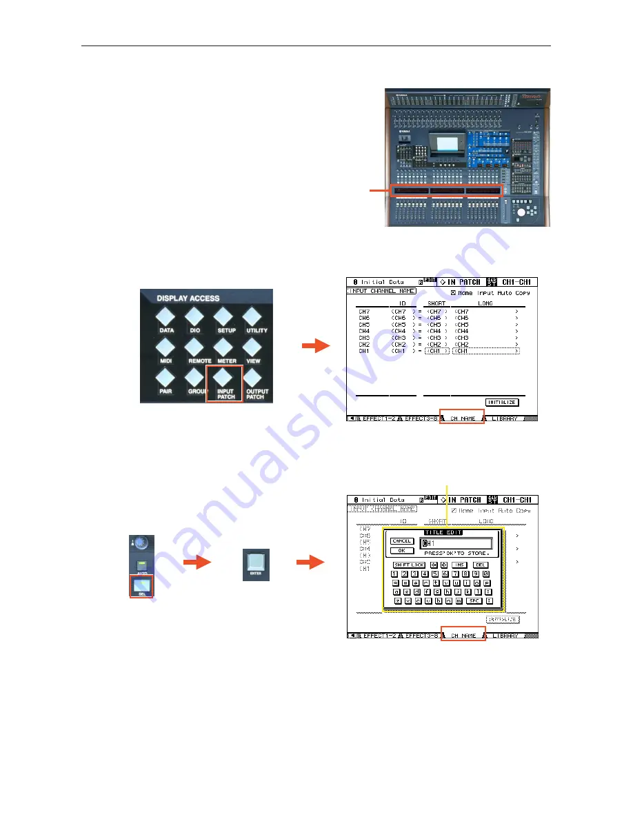
CHANNEL NAMES

Each channel on the DM2000 can be given a name, which is displayed 
in the fluorescent window (

1

) above the faders. Also the name of the 

currently selected channel is always displayed in the top-right corner 
of the LCD.

To input a channel name, first access the CH NAME page by pressing the [INPUT PATCH] DISPLAY ACCESS button.

Then press the [SEL] button for the required channel, and press [ENTER] to display the TITLE EDIT window on the 
LCD. If a computer keyboard is connected to the rear panel, then a name can be typed. Otherwise, use the cursor keys and 
[ENTER] button to navigate around the LCD keyboard.

1

TITLE EDIT window

Summary of Contents for Studio Manager V2 DM2000 Editor

Page 1: ...irst time It is not a guide to audio mixing and it assumes the reader has experience of analog mixers It does not replace the manual we recommend referring to the manual if further information is requ...

Page 2: ...ODE 10 Using the SELECTED CHANNEL controls 11 EQUALIZER 11 PAN 12 DYNAMICS 12 AUX MATRIX SEND 13 ROUTING 15 PHASE INSERT 16 DELAY 16 CHANNEL PAIR 17 FADER GROUPS 18 MUTE GROUPS 18 EFFECTS 19 EDITING A...

Page 3: ...en move down and all the mixing functions set to their default status Understanding the Rear Panel All the audio connectors are on the rear panel They include Other connectors on the rear panel are fo...

Page 4: ...nnel can be selected at any time To select a channel and see its settings in the SELECTED CHANNEL area just press the SEL button Then press the SEL button for another channel when you are ready to mov...

Page 5: ...INPUT PATCH menu Here is the default patch channels 1 24 control the 24 analog inputs on the top on the console channels 25 48 control inputs 1 8 from Slots 1 2 and 3 channels 49 72 control inputs 1 8...

Page 6: ...n to the required channel number 4 Press ENTER by the data wheel at the bottom right corner of the console This will open the PATCH SELECT window 5 Select the type of input from the first list in the...

Page 7: ...he Output Patch press the OUTPUT PATCH DISPLAY ACCESS button and press it again if necessary to view the required SLOT or OMNI page Use the cursor keys to highlight the required output port and press...

Page 8: ...the top right corner of the LCD To input a channel name first access the CH NAME page by pressing the INPUT PATCH DISPLAY ACCESS button Then press the SEL button for the required channel and press ENT...

Page 9: ...he top of the CH NAME page to automatically copy the first 4 characters of the long name to the short name whenever a new long name is entered To enter names for the Buses Auxes and Matrix channels lo...

Page 10: ...differ ent page to see the information for other channels In these pages PRE POST status can be edited and the AUX SENDS can be turned off by pressing ENTER while the cursor is high lighting the Leve...

Page 11: ...is moved the LCD will show the EQ edit page There are 4 parametric bands To change between controlling FREQUENCY and Q press down quickly on the encoder Note that the LOW band can be a Low Shelf or a...

Page 12: ...s press the PAN SURROUND DISPLAY button so the SURR MODE page is shown Then choose the SURROUND MODE 3 1 or 5 1 or 6 1 This will then convert some of the Buses 1 8 into Surround Buses DYNAMICS Each in...

Page 13: ...nu is not shown on the LCD the Send Level will always pop up on the LCD whenever it is adjusted or when the encoder is simply pressed Press the AUX MATRIX SEND DISPLAY button to see the relevant infor...

Page 14: ...e 14 28 PAN controls can also be accessed for any stereo paired Aux and for the Matrix sends which are always stereo These parameters must be edited with the Data Wheel and Cursor Keys in the bottom r...

Page 15: ...the channel will follow through to the Buses This is particularly use ful when using the Buses as stereo Sub Groups as on a typical analog console The Bus assignment is also displayed in the fluoresc...

Page 16: ...he INSERT POSITION can also be changed here DELAY Press the DELAY DISPLAY button to see Delay settings for each channel All input and output channels have a Delay function The maximum possible Delay T...

Page 17: ...e paired with the equivalent channel on the layer below 25 48 In the same way channels 49 72 can be paired vertically with channels 73 96 respectively but the Master chan nels can only be paired Horiz...

Page 18: ...useful for turning On Off many channels by just pressing one button There are 8 Mute Groups avail able for input channels and 4 Mute Groups for output channels To assign channels to a Mute Group foll...

Page 19: ...FFECTS button and then pressing one of the buttons 1 8 below to select the required unit EDITING AN EFFECT The Effect parameters can be edited using the 4 encoders below the LCD Use the Up Down arrow...

Page 20: ...can be used properly it needs to be patched The default patch factory setting has Aux 1 8 patched to the inputs of FX1 8 respectively The stereo outputs of FX1 8 are patched to input channels 73 88 r...

Page 21: ...rn up Aux 1 send level for the required channel 2 Check that the Aux 1 Master fader is up to 0dB that is its default position 3 Already audio should be seen on the level meters of Effect 1 You can see...

Page 22: ...ys inserted post fader and is separate from the standard insert point which can be used for internal or exter nal Effects The channel faders can be used to edit the GEQ bands by moving the cursor onto...

Page 23: ...screen the chosen parameters will be safe in all Scenes Otherwise these settings will only apply to the current Scene once it is stored When a SCENE is stored a name can be entered If a SCENE is PROT...

Page 24: ...ting the Fade Time for one channel double click the ENTER button to copy the time to all Input or Output Channels SCENE COPY PASTE If some settings need to be copied from one Scene to some others the...

Page 25: ...LEVEL adjusts the main listening level The DIMMER button can quickly dim the speakers by 20dB or so 2 The CONTROL ROOM buttons select what to listen to in the Control Room monitors and in the head pho...

Page 26: ...Each Bank is given a Title to describe its general purpose To assign a new function to a USER DEFINED KEY first move the cursor to the relevant field in the USER DEF page Then press ENTER to open the...

Page 27: ...hird time will cancel the SOLO While the AUX is in SOLO its SELECT but ton will flash 5 Copy STEREO Mix to an AUX Press and hold an INPUT FADER LAYER button then press an AUX SELECT button and click Y...

Page 28: ...ders PHANTOM POWER can be controlled from the HA CTRL page in the PHASE INSERT menu 5 SCENE MEMORY Auto Update In the PREFERENCES1 page of the SETUP menu the Scene MEM Auto Update option can be found...

Reviews: