background image

ESU00003 

CONTENTS

YAMAHA MOTOR 
CORPORATION, U.S.A. 
SNOWMOBILE LIMITED 
WARRANTY

.......................................1-1

YAMAHA EXTENDED SERVICE 
(Y.E.S.)

...............................................1-4

LOCATION OF THE 
IMPORTANT LABELS

.......................2-1

SAFETY INFORMATION

...................3-1

DESCRIPTION

...................................4-1

CONTROL FUNCTIONS

....................5-1

Main switch......................................5-1
Throttle lever....................................5-1
Engine overheating prevention 
system .............................................5-2
Throttle override system 
(T.O.R.S.) ........................................5-2
Speedometer unit ............................5-4
High beam indicator light .................5-5
Fuel meter and grip/thumb 
warmer level indicator......................5-6
Fuel level warning indicator .............5-7
Oil level warning indicator................5-7
Low coolant temperature 
indicator light ...................................5-7
Coolant temperature warning 
indicator ...........................................5-8
Self-diagnostic system.....................5-8
Engine stop switch...........................5-9
Brake lever ......................................5-9
Parking brake lever........................5-10
Shift lever.......................................5-10
Rear suspension damping force 
remote adjustment dial ..................5-11
Headlight beam switch ..................5-11
Auxiliary DC jack ...........................5-11

Shroud and covers ........................5-12
Drive guard ....................................5-13
V-belt holders ................................5-13
Storage compartment ....................5-13
Rear carrier ...................................5-13

PRE-OPERATION CHECKS

..............6-1

Fuel .................................................6-1
Engine oil.........................................6-2
Engine oil level ................................6-3
Coolant ............................................6-4
Throttle lever ...................................6-5
Throttle override system 
(T.O.R.S.) ........................................6-5
Brake ...............................................6-6
Brake fluid leakage ..........................6-7
V-belt ...............................................6-7
Drive guard ......................................6-7
Drive track .......................................6-8
51-mm (2.0-in) high-profile pattern 
drive track ........................................6-8
Slide runners ...................................6-9
Skis and ski runners ........................6-9
Steering system.............................6-10
Lights .............................................6-10
Air filter ..........................................6-11
Fittings and fasteners ....................6-12
Tool kit and recommended 
equipment......................................6-12

OPERATION

......................................7-1

Starting the engine ..........................7-1
Break-in ...........................................7-2
Riding your snowmobile ..................7-3
Getting to know your snowmobile ...7-3
Learning to ride your snowmobile ...7-3
To start out and accelerate..............7-3
Braking ............................................7-3
Turning ............................................7-4
Riding uphill .....................................7-4
Riding downhill ................................7-5
Traversing a slope ...........................7-5

E_8fp.book  Page 1  Tuesday, March 28, 2006  4:35 PM

Summary of Contents for RX10RW

Page 1: ...OWNER S MANUAL SNOWMOBILE RX10RW RX10RTRW RX10MW RX10MSW RXW10W 8FP 28199 12 LIT 12628 02 53 PRINTED ON RECYCLED PAPER PRINTED IN JAPAN 2006 04 1 6 1 CR E YAMAHA MOTOR CO LTD ...

Page 2: ......

Page 3: ...he spaces provided for assistance when ordering spare parts from a Yamaha dealer 1 The frame number is the seventeen digit number stamped on the frame of the snowmobile See fig È 2 The engine number is stamped in the location as shown See fig É 3 Key number See fig Ê Also record and keep the ID numbers in a separate place in case the snowmobile is stolen A B C E_8fp book Page 1 Tuesday March 28 20...

Page 4: ...g the operation or maintenance of your snowmobile please consult a Yamaha dealer To maintain the high quality and performance of this snowmobile it is important that you and your Yamaha dealer pay close attention to the recommended mainte nance schedules and operating instructions contained within this manual RX10RW RX10RTRW RX10MW RX10MSW RXW10W OWNER S MANUAL 2006 by Yamaha Motor Corporation U S...

Page 5: ...d a permanent part of this snowmobile and should remain with the snow mobile when resold Particularly important information is distinguished in this manual by the following notations The Safety Alert Symbol means ATTENTION BECOME ALERT YOUR SAFETY IS INVOLVED WARNING Failure to follow WARNING instructions could result in severe injury or death to the snowmobile operator a bystander or a person ins...

Page 6: ...remote adjustment dial 5 11 Headlight beam switch 5 11 Auxiliary DC jack 5 11 Shroud and covers 5 12 Drive guard 5 13 V belt holders 5 13 Storage compartment 5 13 Rear carrier 5 13 PRE OPERATION CHECKS 6 1 Fuel 6 1 Engine oil 6 2 Engine oil level 6 3 Coolant 6 4 Throttle lever 6 5 Throttle override system T O R S 6 5 Brake 6 6 Brake fluid leakage 6 7 V belt 6 7 Drive guard 6 7 Drive track 6 8 51 m...

Page 7: ...h altitude settings 8 11 Adjusting the valve clearance 8 11 Changing the engine oil 8 12 Cooling system 8 14 Replacing the V belt 8 16 Checking the drive chain housing oil level and the drive chain tension 8 19 Checking the brake pads 8 20 Checking the parking brake pads 8 20 Checking the brake fluid level 8 21 Changing the brake fluid 8 22 Suspension 8 22 Adjusting the drive track 8 32 Aligning t...

Page 8: ...normal wear or routine maintenance including oil spark plugs clutch drive belts slide runners and track THE CUSTOMER S RESPONSIBILITY under this warranty shall be to 1 Operate and maintain the snowmobile as specified in the appropriate Owner s Manual 2 Give notice to an authorized Yamaha snowmobile dealer of any and all apparent defects within ten 10 days after discovery and make the machine avail...

Page 9: ...ark plugs clutch drive belts and slide runners Q What are some examples of abnormal strain ne glect or abuse A These terms are general and overlap each other in areas Specific examples include Running the ma chine out of oil hitting an object submerged under snow operation on surfaces other than snow or ice operating the machine with a broken or damaged part which causes another part to fail and s...

Page 10: ...warranty matters are handled at the dealer level this person is in the best position to help you If you are still not satisfied and require additional assistance please write YAMAHA MOTOR CORPORATION U S A CUSTOMER RELATIONS DEPARTMENT P O Box 6555 Cypress California 90630 When contacting Yamaha Motor Corpora tion U S A be sure to include the model serial number names dates and receipts CHANGE OF ...

Page 11: ...1 4 ESU04280 YAMAHA EXTENDED SERVICE Y E S CW 06E E_8fp book Page 4 Tuesday March 28 2006 4 35 PM ...

Page 12: ...se read the following labels carefully before operat ing this snowmobile NOTE Maintain or replace safety and instruction labels as nec essary 1 RX10R RX10RTR RXW10 1 RX10M RX10MS 2 8FB 77761 E0 8EK 77761 E0 E_8fp book Page 1 Tuesday March 28 2006 4 35 PM ...

Page 13: ...MS 6 RXW10 7 RX10M RX10MS 8 RX10M RX10MS 4AA 22259 70 4AA 22259 60 8FN 77761 E0 8ED 2191H E0 8FS 24875 E0 Do not use the carrier to lift the snowmobile Ne pas soulever la motoneige en tirant sur le porte bagages E_8fp book Page 2 Tuesday March 28 2006 4 35 PM ...

Page 14: ...2 3 NOTE The following suspension adjustment charts are included with the Owner s Manual RX10R RXW10 RX10RTR RX10M RX10MS E_8fp book Page 3 Tuesday March 28 2006 4 35 PM ...

Page 15: ... to carry the OPERA TOR ONLY Passengers are prohibited Carrying a passenger can cause loss of control 4 Do not operate the snowmobile after drinking alcohol or taking drugs Your ability to operate the snowmo bile is reduced by the influence of alcohol or drugs 5 For safety and proper care of the snowmobile always perform the pre operation checks on pages 6 1 6 12 before starting the engine Check t...

Page 16: ...e vapor or get some gasoline into your eyes see your doctor immediately If any gasoline spills on your skin or clothing immediately wash your skin with soap and water and change your clothes 10 Wear protective clothing Wear an approved helmet and a face shield or goggles Also wear a good qual ity snowmobile suit boots and a pair of gloves or mit tens that will permit use of your thumbs and fingers...

Page 17: ...lease the throttle and apply the brake gently not suddenly Maintenance and storage 1 Do not leave the snowmobile on its left side for an extended period of time Fuel may leak out from the fuel breather hose 2 Modifications made to the snowmobile not approved by Yamaha or the removal of original equipment may render your snowmobile unsafe for use that may cause severe personal injury Modifications ...

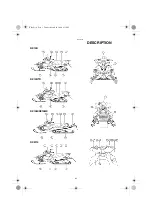
Page 18: ...4 1 ESU00012 4 DESCRIPTION RX10R RX10RTR RX10M RX10MS RXW10 E_8fp book Page 1 Tuesday March 28 2006 4 35 PM ...

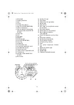
Page 19: ...Throttle lever M Shift lever RX10R RX10RTR RXW10 N Main switch O Auxiliary DC jack P Tachometer Q Mode button not applicable R Reset button S Select button T Fuel meter and grip thumb warmer level indicator U Fuel meter indicator V Self diagnosis warning indicator W Rear suspension indicator not applicable X Coolant temperature warning indica tor Y Grip warmer indicator Z Fuel level warning indica...

Page 20: ...adlights meter lights and taillights come on after the engine starts ESU00022 Throttle lever Once the engine is running cleanly squeezing a the throt tle lever 1 will increase the engine speed and cause engagement of the drive system Regulate the speed of the snowmobile by varying the throttle position Because the throttle is spring loaded the snowmobile will deceler ate and the engine will return...

Page 21: ...s or throttle cable malfunctions during operation the T O R S will operate when the throttle lever is released The T O R S is designed to interrupt the fuel injection and keep the engine speed between 2 800 and 3 000 r min if the throttle valves fail to return to the idle position when the throttle lever is released WARNING If the T O R S is activated make sure that the cause of the malfunction ha...

Page 22: ...l flash and the two digit code 84 6 will flash in the clock dis play The T O R S monitors the condition of the throttle position sensor speedometer assembly and speed sensor and will operate if any of the monitored items is disconnected or malfunctioning A B C Mode Item Idling starting Running Trouble Throttle switch Off On Off Throttle position sensor Closed Open Open Engine Run Run T O R S will ...

Page 23: ...tor light 2 the warning light 3 and all segments of the meter display 4 turn on and off once The grip warmer level is initially displayed for 5 seconds then the display switches to the fuel meter Odometer tripmeter and barometer modes Pushing the SELECT button 1 switches the display between the odometer mode ODO tripmeter modes TRIP A and TRIP B and barometer mode BARO To reset a tripmeter push th...

Page 24: ...y to suit the outdoor lighting conditions To adjust the display brightness 1 Turn the main switch to OFF 2 Push and hold down the SELECT button 1 3 Turn the main switch to ON and then after 5 sec onds release the SELECT button 4 Push the RESET button 2 to select the desired dis play brightness level 3 and then push the SELECT button The normal display returns when the SELECT button is released NOT...

Page 25: ... 2 control the electrically heated handlebar grips and throttle lever respectively To raise the temperature press the respective switch to HI To lower the temperature press the switch to LO NOTE The grip warmer indicator 3 comes on and the dis play switches to the grip warmer level when the grip warmer adjustment switch is pressed The thumb warmer indicator 4 comes on and the display switches to t...

Page 26: ...it to idle for one minute If the oil level warning indicator and the warning light go off the engine oil level is sufficient however it is getting low Add engine oil as soon as possible If the oil level warning indicator and the warning light do not go off check the engine oil level in the oil tank see page 6 3 and add engine oil if necessary ESU04840 Low coolant temperature indicator light The lo...

Page 27: ...the self diagnosis warning indicator 2 will flash and then an error code e g 16 and 81 3 will flash slowly in the tripmeter odometer display WARNING If the self diagnosis warning indicator and warn ing light flash continuously and an error code is displayed during operation there may be some problem with the electrical circuit lead couplers etc Stop the engine and allow it to cool off Then check t...

Page 28: ...r grip to stop the snowmobile 1 Brake lever 2 Brake lever end 3 Handlebar end NOTE When the brake lever is operated the brake light will illu minate CAUTION Make sure that the brake lever end does not project out over the handlebar end This will help prevent brake lever damage when the snowmobile is placed on its side for service The brake lever is equipped with a position adjuster To adjust the b...

Page 29: ...th the parking brake applied This may overheat the brake disc and reduce braking ability ESU03411 Shift lever For RX10R RX10RTR RXW10 The shift lever is used to put the snowmobile into forward or reverse After coming to a complete stop pull the shift lever out slide it to FWD or to REV until it stops and then release it 1 Shift lever 2 Pull out 3 Slide to FWD Forward 4 Slide to REV Reverse 5 Relea...

Page 30: ...am to high or low 1 Headlight beam switch 2 Push 3 High beam 4 Low beam ESU04301 Auxiliary DC jack The auxiliary DC jack is located in the front panel and can be used for accessories NOTE The auxiliary DC jack cannot be used if the engine is not running 1 Start the engine 2 Open the auxiliary DC jack cap 1 and then insert the accessory power plug into the jack 2 NOTE After using the auxiliary DC j...

Page 31: ... operating the snowmobile See pages 8 5 8 7 for removal and installation procedures 1 Shroud 2 Right side cover 3 Left side cover 4 Top cover WARNING Do not drive the snowmobile with the shroud or covers unfastened or removed Keep your body and clothing away from rotating parts when servicing the snowmobile with the shroud or covers removed Do not touch the hot muffler and engine during or immedia...

Page 32: ...ing it into the V belt holders provided CAUTION Make sure that the V belt is installed securely in the holders ESU00680 Storage compartment Open the storage compartment to store the service tools spare parts or other small items ESU05020 Rear carrier For RX10M RX10MS The rear carrier is located at the rear of the snowmobile 1 Rear carrier WARNING Do not use the rear carrier to lift the snowmobile ...

Page 33: ...nk WARNING Fuel is HIGHLY FLAMMABLE and poisonous Check the SAFETY INFORMATION section carefully before refueling See page 3 2 Do not fill the fuel tank above the bottom of the filler tube 1 Fuel could overflow if the snowmo bile is tilted or if the ambient temperature rises causing the fuel to warm up and expand Make sure that the fuel tank cap is closed securely after refueling Leaking fuel can ...

Page 34: ...enter the fuel tank when refueling Do not use alcohol deicers or water absorbing additives with oxygenated fuel The fuel tank should be filled with straight gaso line as specified ESU04031 Engine oil Use a combination of the recommended SAE and API oil classifications shown in the chart below CB 02E CAUTION Use only 4 stroke engine oil SAE API SE SF SG or higher 40 20 0 20 40 60 F SAE 0W 30 40 29 ...

Page 35: ...econds before turning it off 3 Remove the shroud and the right side cover See pages 8 5 8 7 for removal procedures 4 Disconnect the oil level gauge coupler 1 CAUTION Disconnect the oil level gauge coupler before remov ing the oil level gauge dipstick Otherwise the cable can twist and break 5 Remove the oil level gauge dipstick 2 wipe it clean insert it back into the oil filler hole without screwin...

Page 36: ...op cover See pages 8 5 8 7 for removal procedures 2 Check the coolant level in the coolant recovery tank when the engine is cold If the coolant level is below the COLD LEVEL mark add soft water until it reaches the COLD LEVEL mark See pages 8 14 8 16 for more details 1 COLD LEVEL mark WARNING Do not remove the coolant reservoir cap when the engine is hot 2 Coolant reservoir cap CAUTION Hard water ...

Page 37: ...orward unexpectedly which could cause an accident 1 Start the engine NOTE Refer to the Starting the engine section 2 Hold the pivot point of the throttle lever away from the throttle switch by putting your thumb above and forefinger below between the throttle lever pivot 1 and the engine stop switch housing 2 While holding the pivot point as described above press the throttle lever 3 gradually The...

Page 38: ...rake system Do not operate the snowmobile if you find any problems in the brake system You could lose braking ability which could lead to an accident Ask a Yamaha dealer to inspect and repair the brake system CAUTION Make sure that the brake lever end does not project out over the handlebar end This is to prevent brake lever damage when the snowmobile is placed on its side 2 Brake fluid Check the ...

Page 39: ...20 V belt Check the V belt 1 Remove the shroud and the left side cover and then remove the drive guard See pages 8 5 8 7 for removal procedures 2 Check the V belt for wear and damage Replace if necessary 3 Install the left side cover and the shroud WARNING Make sure that the drive guard is installed securely before operating the snowmobile Never run the engine with the V belt or drive guard remove...

Page 40: ...ile pattern drive track For RX10M RX10MS This snowmobile is originally equipped with a 50 mm 2 0 in high profile pattern drive track specifically for use in deep snow riding conditions Therefore avoid prolonged operation on hard surfaces such as ice hard packed snow dirt etc to extend the life of the track and slide runners CAUTION Only use in deep snow riding conditions Operation on areas with li...

Page 41: ...skis and ski runners for wear and damage Replace if necessary CAUTION Avoid scratching the skis when loading and unload ing the snowmobile when riding in areas with little or no snow or on sharp edges such as concrete curbs etc This will wear or damage the skis Wear limit height 10 5 mm 0 41 in For RX10 RX10RTR RXW10 Ski runner wear limit a 8 mm 0 31 in Ski wear limit b 12 mm 0 47 in For RX10M RX1...

Page 42: ...back and forth 2 Turn the handlebar slightly to the right and left If excessive free play is noticed consult a Yamaha dealer ESU00378 Lights Check the lights Replace any burned out bulbs CAUTION Avoid using a scraper or hot water for cleaning the plastic lenses 1 E_8fp book Page 10 Tuesday March 28 2006 4 35 PM ...

Page 43: ...nt and brush off the snow and then install the air filter element 6 Place the air filter element frame in its original posi tion and then install the air filter case cover Hook the fasteners onto the air filter case cover 7 Install the headlight unit making sure to insert the tabs on the headlight unit stay into the slots on the bottom of the headlight unit 8 Install the headlight unit bolts and t...

Page 44: ...l kit spare parts and other necessary equipment with you while riding the snowmobile so that minor repairs can be done if neces sary The following should be carried at all times Tool kit Flashlight Roll of plastic tape Steel wire Towrope Jumper cables V belt Light bulbs Spark plugs When you start out for a long distance trip extra fuel and oil should be carried as well E_8fp book Page 12 Tuesday M...

Page 45: ...operated when the engine stop switch is in the off position 1 Turn the main switch to the START position Warm up the engine until it does not run roughly 1 START CAUTION Release the switch immediately after the engine starts If the engine fails to start release the switch wait a few seconds then try again Each attempt should be as short as possible to preserve the battery Do not crank the engine m...

Page 46: ... any condition that might result in engine overheating must be avoided Operating your snowmobile for the first time Start the engine and let it idle for 15 minutes 0 160 km 0 100 mi Avoid prolonged operation above 6 000 r min 160 500 km 100 300 mi Avoid prolonged operation above 8 000 r min 500 km 300 mi and beyond The snowmobile can now be operated normally CAUTION After 800 km 500 mi of operatio...

Page 47: ...d a more reliable snowmobile Always wear the proper cloth ing for both warmth and to help protect you from injury if an accident occurs Become familiar with operating your snow mobile at low speeds even if you are an experienced rider Do not attempt to oper ate at maximum performance until you are totally familiar with the snowmobile s han dling and performance characteristics Set the parking brak...

Page 48: ...th the operation of your snowmobile Riding uphill You should practice first on gentle slopes Try more difficult climbs only after you have developed your skill As you approach a hill accelerate before you start the climb and then reduce the throttle to prevent track slippage It is also important to keep your weight on the uphill side at all times On climbs straight up the hill this can be accompli...

Page 49: ...seat and the foot of your uphill leg on the running board This position will make it easier for you to shift your body weight as needed Snow and ice are slippery so be prepared for the possibility that your snowmobile could begin to slip sideways on the slope If this happens steer in the direction of the slide if there are no obstacles in your path As you regain proper balance gradually steer agai...

Page 50: ...ot of dirt and sand All of the above surfaces have one thing in common in regard to drive track and slide runners little or no lubricating ability Drive track and all slide rail systems require lubrication snow or water between the slide runners and the slide metal In the absence of lubrication the slide runners will rapidly wear and in severe cases liter ally melt away and the drive track will be...

Page 51: ...d high speed usage in areas such as icy trails frozen lakes and rivers that have minimal snow coverage An overheated track will be weakened internally which may cause fail ure or damage Off trail riding Avoid off trail riding until there is sufficient snow cover age It generally takes several feet of snow to provide a good overall base to properly cover debris such as rocks logs etc If snow covera...

Page 52: ...g traverse side hill riding Only experi enced operators should traverse slopes steep enough to require strap use Keep the right hand on the right handlebar grip for steering and grip the strap with the left hand to shift weight uphill for balance during traverse riding Ride cautiously while using the strap Do not accelerate or decelerate abruptly while holding onto the strap Do not use the strap t...

Page 53: ...g the parking brake lever to the left For RX10R RX10RTR RXW10 1 To select the desired operating position pull the shift lever out slide it to FWD or to REV until it stops and then release it 1 Pull out 2 Slide to FWD Forward 3 Slide to REV Reverse 4 Release WARNING Make sure that the throttle lever is fully released and the snowmobile is at a full stop before shift ing Be sure to slide the shift l...

Page 54: ...owmo bile 4 Turn the handlebar in the desired direction 5 Squeeze the brake lever to stop the snowmobile 6 Apply the parking brake by moving the parking brake lever to the left ESU00136 Stopping the engine Turn the main switch to the OFF position to stop the engine 1 OFF WARNING Push down the engine stop switch to stop the engine in an emergency Make sure that the key is removed from the main swit...

Page 55: ...le is best This will help keep foreign objects out of the cooling vents in the shroud and also help protect the snowmobile against damage from debris on the road If transporting the snowmobile in an open trailer or truck in areas where road salt is used coat metal suspension surfaces lightly with oil or another pro tectant This will help protect against corrosion Be sure to clean the snowmobile wh...

Page 56: ...NOT ONLY ENSURE CLEANER AIR BUT ARE ALSO VITAL TO PROPER ENGINE OPERATION AND MAXIMUM PERFORMANCE IN THE FOLLOWING PERI ODIC MAINTENANCE CHARTS THE SERVICES RELATED TO EMISSIONS CONTROL ARE GROUPED SEPARATELY THESE SERVICES REQUIRE SPECIALIZED DATA KNOWLEDGE AND EQUIPMENT YAMAHA DEALERS ARE TRAINED AND EQUIPPED TO PERFORM THESE PARTICULAR SERVICES ESU04970 Periodic maintenance chart for the emissi...

Page 57: ...level 6 1 6 2 Engine coolant Check coolant level recovery tank 6 4 Check coolant level reservoir tank 8 15 8 16 Air bleed the cooling system if necessary 8 14 Throttle lever handlebar side Check operation Repair if necessary 5 1 6 5 Throttle override system T O R S Check operation Repair if necessary 5 2 6 5 Engine stop switch Check operation Repair if necessary 5 9 Drive guard Check for cracks be...

Page 58: ...y 800 km 500 mi thereafter 8 20 Skis and ski runners Check for wear and damage 6 9 Replace if necessary Steering system Check operation 6 10 Adjust toe out if necessary Strap RX10M RX10MS Check for damage Replace if necessary Lights Check operation Replace bulbs if necessary 6 10 8 36 8 37 Battery Check condition Charge if necessary 8 37 Primary and second ary clutches Check engagement and shift s...

Page 59: ...sion component Lubricate with specified grease 8 35 Parking brake cable end and lever end throttle cable end Lubricate with specified grease 8 35 Check cable damage Replace if necessary Shroud and covers Make sure that the shroud and covers are securely fastened 5 12 8 5 8 7 Fittings and fasteners Check tightness Repair if necessary 6 12 Tool kit and recom mended equipment Check for proper placeme...

Page 60: ...vailable during a service operation requiring one take your snowmobile to a Yamaha dealer to check the torque settings and adjust them if necessary ESU04502 Removing and installing the shroud and covers Shroud To remove the shroud Turn the fasteners counterclockwise slowly raise the shroud and then unhook the shroud from the shroud stay 1 Fastener 2 Shroud To install the shroud Hook the end of the...

Page 61: ...Top cover To remove the top cover 1 Remove the screws and then remove the cable guide 2 Remove the bolts disconnect the main switch cou pler and auxiliary DC jack coupler and then remove the top cover 1 Screws 2 Cable guide 3 Bolts 4 Top cover To install the top cover 1 Connect the main switch coupler and auxiliary DC jack coupler place the top cover in its original posi tion and then install the ...

Page 62: ...he condition of the engine Check the coloration on the white porcelain insulator around the center electrode The ideal coloration at this point is a medium to a light tan color for a snowmobile that is being ridden normally If a spark plug shows a distinctly different color there could be something wrong with the engine For example a very white center electrode porcelain color could indi cate an i...

Page 63: ... damage Always use a spark plug with the speci fied reach Before installing any spark plug measure the electrode gap with a wire thickness gauge and adjust to specifica tion When installing the spark plug always clean the gasket surface Wipe off any grime from the threads and tighten the spark plug to the specified torque CAUTION Make sure that the spark plug caps are securely installed Otherwise ...

Page 64: ...ift up the headlight unit 4 Turn the idle adjusting screw 2 in or out to adjust the engine idling speed 5 Install the headlight unit making sure to insert the tabs on the headlight unit stay into the slots on the bottom of the headlight unit 6 Install the headlight unit bolts and then tighten them to the specified torque 7 Install the top cover the left and right side covers and the shroud Standar...

Page 65: ...y is achieved 1 Headlight unit bolt 2 Locknut 3 Adjuster 6 Tighten the locknut 7 Connect the speedometer coupler and headlight cou plers and then install the headlight unit making sure to insert the tabs on the headlight unit stay into the slots on the bottom of the headlight unit 8 Install the headlight unit bolts and then tighten them to the specified torque 9 Install the top cover bolts 10 Inst...

Page 66: ...come operating with less power at high altitudes your snowmobile may also require different settings for the drive chain gears and V belt clutch to avoid poor per formance and rapid wear If you plan to operate your snowmobile at an altitude different from the area where you bought it be sure to consult a Yamaha dealer The dealer can tell you if there are any changes necessary for the altitude wher...

Page 67: ...2 000 mi of operation Have a Yamaha dealer replace the oil filter cartridge To change the engine oil without oil filter cartridge replacement 1 Place the snowmobile on a level surface and apply the parking brake 2 Start the engine warm it up for several minutes and then turn it off 3 Remove the shroud and the right side cover See pages 8 5 8 7 for removal procedures 4 Remove the bottom panel 1 and...

Page 68: ...ure that no foreign material enters the engine oil tank 12 Start the engine and then let it idle for several min utes while checking it for oil leakage If oil is leaking immediately turn the engine off and make sure that the engine oil drain bolts and oil level gauge dipstick are installed correctly 13 Turn the engine off and then connect the oil level gauge coupler Tightening torques Crankcase en...

Page 69: ...own out under pressure which could cause serious injury When the engine has cooled place a thick rag or towel over the coolant reservoir cap and slowly rotate the cap counterclockwise to the detent This procedure allows any residual pressure to escape When the hissing sound has stopped press down on the cap while turning counter clockwise and remove it The cooling system must be bled of air if the...

Page 70: ...ty if air can be seen in the cooling system or if there is a cooling system leak Consult a Yamaha dealer 1 Remove the top cover See pages 8 5 8 7 for removal procedures 2 Remove the coolant reservoir cap fill the reservoir with the recommended coolant and then install the cap 3 Remove the coolant recovery tank cap add the rec ommended coolant until it reaches the COLD LEVEL mark and then install t...

Page 71: ...in below the edge a If not the V belt clutch engagement speed will be changed The snowmobile may move unexpectedly when the engine is started Adjust the V belt position by removing or adding a spacer 1 on each adjusting bolt Have a Yamaha dealer make this adjustment CAUTION As the V belt wears adjustment may be necessary To ensure proper clutch performance the V belt position should be adjusted by...

Page 72: ...eave 5 Remove the V belt from the secondary sheave assembly and primary sheave assembly 6 Temporarily install the new V belt on the secondary sheave assembly only and then measure the V belt position Do not force the V belt between the sheaves the secondary sliding and fixed sheaves must touch each other Standard V belt position a From 1 5 mm 0 06 in above the edge of the second ary sheave assembl...

Page 73: ...ll the V belt 8 between the secondary sliding and fixed sheaves 12 Install the drive guard 13 Install the left side cover and the shroud WARNING Never run the engine with the V belt or drive guard removed V belt position Adjustment More than 1 5 mm 0 06 in above the edge Remove spacer From 1 5 mm 0 06 in above the edge to 0 5 mm 0 02 in below the edge Not necessary It is correct More than 0 5 mm 0...

Page 74: ...t it back into the filler hole 4 Remove the dipstick and check that the oil is between the maximum and minimum level marks If the oil is below the minimum level mark add sufficient oil to raise it to the maximum level mark 2 Maximum level mark 3 Minimum level mark È For models without reverse transmissions RX10M RX10MS É For models with reverse transmissions RX10R RX10RTR RXW10 CAUTION Make sure t...

Page 75: ...eck the brake pads for wear If the brake pads reach the wear limit ask a Yamaha dealer to replace them 1 Brake pad wear indicator ESU00352 Checking the parking brake pads Check the parking brake pads for wear by measuring the thickness of the pads If the parking brake pads reach the wear limit ask a Yamaha dealer to replace them Adjustment As the parking brake pads wear adjustment may be nec essar...

Page 76: ...e brake fluid is above the lower level and replenish when necessary 1 Lower level WARNING Be careful that water does not enter the master cylin der when refilling Water will significantly lower the boiling point of the fluid and may result in vapor lock If the brake fluid level goes down consult a Yamaha dealer CAUTION Brake fluid may deteriorate painted surfaces or plas tic parts Never spill any ...

Page 77: ...example may provide greater rider comfort while a harder setting may allow more precise handling and control over certain types of terrain or riding conditions WARNING Be sure to have a Yamaha dealer make this adjust ment ESU01912 Adjusting the ski spring preload The spring preload can be adjusted by turning the spring preload adjuster 1 For RX10R RXW10 CD 11E Spring seat length Standard Increased...

Page 78: ...orber Do not subject the shock absorber to an open flame or other high heat source which could cause it to explode Do not deform or damage the shock absorber in any way Do not dispose of a worn or damaged shock absorber by yourself Take the unit to a Yamaha dealer Spring seat length Standard Increased Decreased Preload Harder Softer a Length Maximum 144 6 mm 5 69 in 134 6 mm 5 30 in Minimum 134 6 ...

Page 79: ...ARNING Support the snowmobile securely on a suitable stand before adjusting the shock absorbers CAUTION Make sure that there is no load on the shock absorb ers and that they are fully extended before making any air pressure adjustments 3 Remove the air valve cap 2 from the shock absorber 4 Install the hose connector 3 of the special pump onto the air valve of the shock absorber and tighten it appr...

Page 80: ...connector the sound of air escaping may be heard but this is from the pump hose not the shock absorber CAUTION Do not exceed 1 034 kPa 10 3 kgf cm2 150 psi 7 Install the air valve cap NOTE If the front suspension bottoms too easily or rolls too much during cornering increase the air pressure by 34 kPa 0 3 kgf cm2 5 psi If the suspension is too firm and you want a more compliant ride decrease the a...

Page 81: ...aha dealer ESU04045 Adjusting the rear suspension spring preload The rear suspension spring preload can be adjusted by turning the spring preload adjuster 1 on the shock absorber RX10R RXW10 or each shock absorber RX10RTR RX10M RX10MS For RX10RTR CD 17E For RX10M RX10MS CD 13E A Spring seat length Standard Increased Decreased Preload Harder Softer È a Length front Maximum 127 5 mm 5 02 in 113 5 mm...

Page 82: ...plode by improper handling causing injury or property damage Do not tamper with or attempt to open the shock absorber Do not subject the shock absorber to an open flame or other high heat sources which could cause it to explode Do not deform or damage the shock absorber in any way Do not dispose of a worn or damaged shock absorber by yourself Take the unit to a Yamaha dealer C Spring adjuster posi...

Page 83: ...tment dial at a marked position around the dial where there is a click WARNING This shock absorber contains highly pressurized nitrogen gas It could explode by improper handling causing injury or property damage Do not tamper with or attempt to open the shock absorber Do not subject the shock absorber to an open flame or other high heat source which could cause it to explode Do not deform or damag...

Page 84: ...NING This shock absorber contains highly pressurized nitrogen gas It could explode by improper handling causing injury or property damage Do not tamper with or attempt to open the shock absorber Do not subject the shock absorber to an open flame or other high heat source which could cause it to explode Do not deform or damage the shock absorber in any way Do not dispose of a worn or damaged shock ...

Page 85: ...tool kit as shown Make sure that the rim d of the control rod body is within the range e of the scale 4 Tighten the locknut while holding the adjuster in place CAUTION When using the special wrench make sure that it is situated at a right angle to the control rod and that it is tightly fitted to the locknut or the control rod adjuster WARNING Never adjust the control rod beyond the range of the sc...

Page 86: ... that they are situated at a right angle to the control rod as shown and that they are tightly fitted to the locknut and the control rod adjusting nut The left and right adjusting nuts must be set to the same position Uneven settings can cause poor handling and loss of stability WARNING Never adjust the control rods beyond the maximum range indicated on the rods with red paint 3 c Adjustable range...

Page 87: ...Replace the drive track if it is damaged to the depth where fabric reinforcement material is visible or support rods are broken Otherwise track damage or failure could result in loss of braking ability and snow mobile control which could cause an accident Measuring the drive track deflection 1 Lay the snowmobile on its side 2 Measure the drive track deflection with a spring scale Pull at the cente...

Page 88: ...wo turns Stop the engine 4 Check the drive track alignment with the slide runners 2 If the alignment is incorrect align the drive track by turning the left and right adjusters CD 08E 7 Slide runners 8 Drive track 9 Slide metal a Gap b Forward 5 Adjust the drive track deflection to specification CD 09E 5 6 Drive track alignment 5 Shifted to right 6 Shifted to left 3 Left adjuster Turn out Turn in 4...

Page 89: ...e rear axle nut ESU02001 Aligning the skis 1 Turn the handlebar so the skis face straight ahead 2 Check the following for ski alignment a Skis are facing forward b Ski toe out 1 2 is within specification 3 If the alignment is not correct consult a Yamaha dealer Rear axle tightening torque 75 Nm 7 5 m kgf 54 2 ft lb Ski toe out 1 2 0 15 mm 0 0 59 in E_8fp book Page 34 Tuesday March 28 2006 4 35 PM ...

Page 90: ...able end only Do not grease the throttle cable because it could become frozen which could cause loss of control 2 Front suspension 3 Rear suspension WARNING Be sure to have a Yamaha dealer lubricate the front and rear suspensions 2 2 Lubricant Low temperature grease 3 3 E_8fp book Page 35 Tuesday March 28 2006 4 35 PM ...

Page 91: ...ING Keep flammable products and your hands away from the hot bulb until it has cooled down 7 Install the new bulb and then hook the bulb holder onto the headlight unit 8 Install the bulb holder cover and then connect the headlight coupler 9 Install the headlight access panel and the top cover CAUTION Keep oil and your hands away from the glass part of the bulb or its life and illumination will be ...

Page 92: ...ep in mind that the battery tends to discharge more quickly if the snowmobile is equipped with electrical accessories WARNING Battery electrolyte is poisonous and dangerous It contains sulfuric acid and can cause severe burns Avoid contact with skin eyes or clothing ANTIDOTE EXTERNAL Flush with water INTERNAL Drink large quantities of water or milk Follow with milk of magnesia beaten egg or vegeta...

Page 93: ...procedures 2 Remove the headlight unit bolts 1 disconnect the headlight couplers and speedometer coupler and then remove the headlight unit 3 Unhook the latch 2 and disconnect the air tempera ture sensor coupler 3 4 Loosen the joint clamp screws 4 5 Slide the clamps 5 away from the air filter case and then disconnect the crankcase breather hose 6 and the bypass air hose 7 6 Slide the clamp 8 down ...

Page 94: ...e specified torque 14 Install the top cover the left and right side covers and the shroud NOTE If the fuse immediately blows again ask a Yamaha dealer to inspect the snowmobile Specified fuses 0Main fuse 40 A AFuel injection system fuse 10 A B HEAD Headlight fuse 20 A C SIG Signal fuse 10 A D DC TERM Auxiliary DC jack fuse 3 A E IGN Ignition fuse 20 A F BACK UP Backup fuse 3 A G FAN Radiator fan f...

Page 95: ...iately for repair 3 Compression Insufficient Loose cylinder head nuts Tighten nuts properly Worn or damaged gasket Replace gasket Worn or damaged piston and cylinder Ask a Yamaha dealer to inspect B Starting the engine with a dis charged battery If the snowmobile battery is discharged the engine can be started using a 12 volt battery and jumper cables Two connecting leads have been provided for ju...

Page 96: ...ctions 4 Pull the red connecting lead cover to expose the terminal through the slit in the cover and then connect the red jumper cable to the red connect ing lead 5 Connect the other end of the red jumper cable to the positive terminal of the booster battery 6 Connect the black jumper cable to the negative terminal of the booster battery 7 Pull the black connecting lead cover to expose the termina...

Page 97: ...y wire connections Check con nections or ask a Yamaha dealer to inspect 3 Discharged battery Charge battery or see B above 4 Seized engine Seizure is caused by poor lubrication inadequate fuel or an air leak Ask a Yamaha dealer to inspect D Engine power is low 1 Low coolant temperature indicator light is flashing Warm the engine up 2 Faulty spark plugs Clean or replace the spark plugs 3 Improper f...

Page 98: ...aler to inspect 2 Incorrect V belt clutch settings for alti tude or conditions Ask a Yamaha dealer to inspect 3 Worn or sticking primary sheave assembly Ask a Yamaha dealer to inspect 4 Worn or sticking secondary sheave assembly Ask a Yamaha dealer to inspect K Noise or excessive vibration in drive chain and sprockets 1 Broken V belt clutch components Ask a Yamaha dealer to inspect 2 Worn or damag...

Page 99: ...the fuel increases the chance for water to enter the engine Use Yamaha Stor Rite Engine Fogging Oil or an equiva lent fogging oil to protect both the com bustion chamber and crankshaft from corrosion An alternate method is to remove the intake silencer and squirt oil into the throttle bodies while the engine is running CAUTION Do not attempt to store the snowmobile by simply starting the engine oc...

Page 100: ...rect sunlight Put a fab ric cover over the snowmobile preferably one that is designed for it Do not use a plastic or vinyl cover condensation could be trapped underneath which could increase the chances of rusting Returning to service after storage When returning your snowmobile to ser vice install the V belt and battery and adjust the drive track Remove the spark plugs and clean or replace them i...

Page 101: ...62 kg 578 lb RX10R 260 kg 573 lb RX10RTR 282 kg 622 lb RX10M 281 kg 619 lb RX10MS 269 kg 593 lb RXW10 Ski stance 1 086 mm 42 7 in RX10R RX10RTR RXW10 980 mm 38 6 in RX10M RX10MS RX10R RX10RTR RX10M RX10MS RXW10 Type Liquid cooled 4 stroke 20 valves Cylinder arrangement Parallel 4 cylinder Displacement 998 cm3 Bore Stroke 74 0 58 0 mm 2 91 2 28 in Idle speed 1 500 100 r min Engine oil type API SE S...

Page 102: ...eeth RX10M RX10MS Transmission Type Automatic centrifugal engagement infinite ly variable 3 8 1 1 1 Sheave distance Approx 268 5 mm 10 57 in Sheave offset Approx 15 mm 0 59 in Engagement speed 1 Approx 3 500 r min Shift speed 1 Approx 10 500 r min 2 Drive chain Silent chain enclosed in oil bath Reduction ratio 38 24 1 58 RX10R RX10RTR 40 20 2 00 RX10M RX10MS 38 23 1 65 RXW10 Fuel tank Tank capacit...

Page 103: ...RX10MS RXW10 Ignition system TCI Spark plug Type R CR9EB NGK Gap 0 7 0 8 mm 0 028 0 031 in Battery Capacity YTX14 BS 12 V 12 A h Maximum charge rate 1 2 Amperes hr for 10 hrs Headlight Bulb Quantity 12 V 60 55 W 2 Tail brake light Bulb Quantity LED Meter light Bulb Quantity LED Indicator light Bulb Quantity LED RX10R RX10RTR RX10M RX10MS RXW10 E_8fp book Page 3 Tuesday March 28 2006 4 35 PM ...

Page 104: ... Y B Y L W R W R W O W O L Lg W Lg B G W Br W B L G B L B O B W B P W L R R L R B Gy R O G Br Y Gy Br L Y G Lg Lg Y L W P B G O Gy R R W O G G O Gy R R W O G O G G O B Ch Y L R W R L R L R L R L G B L B O B R B B R L F R L R L F B B BLACK BLACK B L W B L W B L L Y B L L P W B L L E R B R B E G B G B E L B L B E O B O B E B L B L E Y Y E L L L P B L B L G W Br W B L L P W B L BLACK L P B L L R L R ...

Page 105: ...Low coolant temperature indicator light e Warning light f Headlight relay g Headlight h Headlight beam switch i Radiator fan relay j Radiator fan motor k Auxiliary DC jack l DC TERM Auxiliary DC jack fuse m HEAD Headlight fuse n SIG Signal fuse o FAN Radiator fan fuse p BACK UP Backup fuse q IGN Ignition fuse r Load control relay È RX10R RX10RTR RXW10 É RX10M RX10MS COLOR CODE B Black Br Brown Ch ...

Page 106: ... MEMO E_8fp book Page 3 Tuesday March 28 2006 4 35 PM ...

Page 107: ......

Page 108: ...OWNER S MANUAL SNOWMOBILE RX10RW RX10RTRW RX10MW RX10MSW RXW10W 8FP 28199 12 LIT 12628 02 53 PRINTED ON RECYCLED PAPER PRINTED IN JAPAN 2006 04 1 6 1 CR E YAMAHA MOTOR CO LTD ...

Reviews: