


(1 BD/DVD)
ZONE 3
(SINGLE)
AV 1
AV 2
A
B
AV 1
AV 2
A
B
MON.OUT/ZONE OUT
ZONE2/ZONE3
SURROUND
SURROUND BACK/
SPEAKERS
CE
AV 1
HDMI OUT
AV 2
AV 3
AV 4
HDMI
AV 5
SINGLE
BI-AMP
EXTRA SP2
1
2
4
AV 3
AV 4
CAL
OPTICAL
AUDIO 1
(2 TV)
(3 CD)
AUDIO 2
AUDIO 3
AUDIO 4
FRONT
SURROUND
SUR. BACK
SUBWOOFER
CENTER
MULTI CH INPUT
COMPONENT VIDEO
COAXIAL
MONITOR OUT/ZONE OUT
ZONE OUT
PRE OUT
ZONE 2
FRONT/
F. PRESENCE
AV OUT
e
f
Y
P
B
P
R
Y
P
B
P
R
Y
P
B
P
R
C
D
SURROUND
SUR. BACK
IN
1
MON.OUT/ZONE OUT
ARC
ARC
SELECTABLE
(1 BD/DVD)
ZONE 3
(SINGLE)
A
AV
V
A
A
A
A 1
1
A
AV
V
A
A
A
A 2
2
A
A
B
B
ZONE2/Z
// ONE3
SURROUND
SURROUND BACK/
K
K
SPEAKERS
CE
AV
A
A 1
AV
A
A 2
AV
A
A 3
AV
A
A 4
HDMI
AV
A
A 5
SINGLE
BI-AMP
EXTRA SP2
4
AV
A
A 3
AV
A
A 4
CAL
OPTICAL
AUDIO 1
(2 TV)
(3 CD)
AUDIO 2
AUDIO 3
AUDIO 4
FRONT
SURROUND
SUR. BACK
SUBWOOFER
CENTER
MULT
L
L I CH INPUT
COMPONENT VIDEO
COAXIAL
ZONE OUT
PRE OUT
ZONE 2
FRONT/
TT
F.
FF PRESENCE
AV
A
A OUT
e
f
Y
P
B
P
R
Y
P
B
P
R
C
D
SURROUND
SUR. BACK
IN
1
VIDEO
COMPONENT
VIDEO
V
P
R
Y
V
HDMI
P
R
Y
P
B
P
B
HDMI
HDMI
S VIDEO
S
S
A
When the HDMI input is
available.*
B
When the component
video input is available.
D
When only the video input
is available.
C
When the S-video input is
available.
- 4 -
2
2
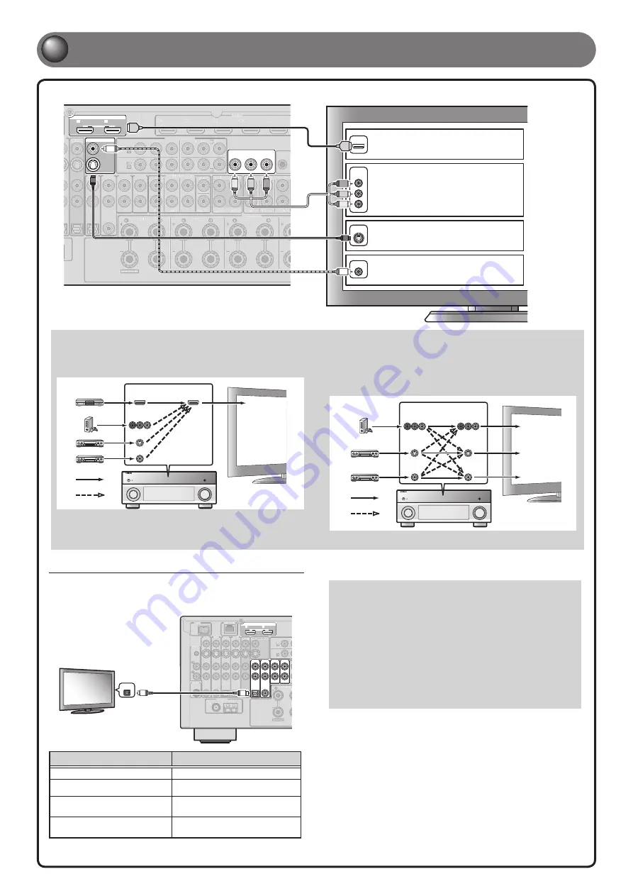
Connect a TV
Listening to TV audio
To play back TV audio on this unit, connect the TV audio output to this unit.
Connect the following input jacks, matching the audio output jacks on your TV.
When viewing your TV, select the appropriate input source on this unit.
SIRIUS
HD Radio
GND
AM
FM
(4 RADIO)
AV 1
AV 2
A
B
AV 1
AV 2
A
B
MON.OUT/ZONE OUT
ZONE2/ZONE
ANTENNA
75
HDMI OUT
EXTRA SP2
1
2
PHONO
GND
(1 BD/DVD)
AV 1
DOCK
NETWORK
AV 2
AV 3
AV 4
COAXIAL
COAXIAL
OPTICAL
OPTICAL
OPTICAL
AUDIO 1
(2 TV)
(3 CD)
AUDIO 2
AUDIO 3
AUDIO 4
F
COAXIAL
AV OUT
a
b
c
d
e
f
Y
MON.OUT/ZONE OUT
ARC
ARC
SELECTABLE
SIRIUS
HD Radio
GND
AM
FM
(4 RADIO)
A
AV
V
A
A
A
A 1
1
A
AV
V
A
A
A
A 2
2
A
A
B
B
ZONE2/Z
// ONE
ANTENNA
75
EXTRA SP2
PHONO
GND
(1 BD/DVD)
AV
A
A
1
DOCK
NETWORK
AV
A
A
2
AV
A
A
3
AV
A
A
4
F
OPTICAL
OPTICAL
COAXIAL
COAXIAL
AV
A
A OUT
a
a
b
c
d
Y
M
MO
ON
N..O
OU
UT
T//
T
T
T
T Z
Z
/////// O
ON
NE
E O
OU
UT
T
OPTICAL
O
O
Audio
output
Audio output from TV
Input jack on this unit
Optical digital output
AUDIO1
Coaxial digital output
AUDIO2
Analog output
AUDIO1, AUDIO2, AUDIO3, or
AUDIO4
HDMI Audio Return Channel
(Described in the right column)
HDMI OUT 1 or HDMI OUT 2
✽
Connecting to AUDIO1 allows you to playback TV audio just by pressing
the
SCENE2
key.
When using a TV that supports the Audio Return Channel
function and HDMI Control function
When using an HDMI compatible TV that supports
Audio Return Channel functions and / or HDMI Control functions
(e.g., Panasonic VIERA Link), you can enjoy the TV sound on this
unit.
The audio / video output from the unit to the TV and audio output
from the TV to the unit are possible using a single HDMI cable.
The input source is switched automatically to match operations
carried out on the TV, and that makes TV sound control easier to
use.
For the connections and settings, refer to “Using the HDMI Control
function” in the Owner’s Manual.
If your TV has multiple inputs, connect with the following priority (
A
to
D
).
When connecting to an HDMI compatible TV
Video signal such as component video, S-video and video received by
this unit is converted to HDMI and output to the TV. Just select HDMI
input on the TV to view video from any external source connected to
this unit.
HDMI
COMPONENT
VIDEO
HDMI
VIDEO
S VIDEO
Input
Output
HDMI input
Through
Converted
TV
When connecting to a non-HDMI compatible TV
Connect to the TV using the same type of connection that you used to
connect to the playback device.
If the playback device and TV are equipped with different types of
analog video jacks, this unit will convert the video signals to another
type of video signal, according to the type of video input jacks used
on the TV.
COMPONENT
VIDEO
COMPONENT
VIDEO
VIDEO
VIDEO
S VIDEO
S VIDEO
Input
Output
Component
video input
Video input
S-video input
Through
Converted
TV
For more information on video signal conversion, refer to “Connecting a TV monitor” in the Owner’s Manual.
* For details on selecting the active HDMI OUT jack, refer to
“Selecting the active HDMI OUT jack” in the Owner’s Manual.


