


ENGINE
3-6
b. Calculate the difference between the speci-
fied valve clearance and the measured
valve clearance.
Example:
Specified valve clearance = 0.11–0.20 mm
(0.004–0.008 in)
Measured valve clearance = 0.23 mm
(0.009 in)
0.23 mm (0.009 in) – 0.20 mm (0.008 in) =
0.03 mm (0.001 in)
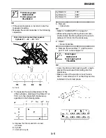
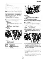
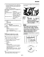
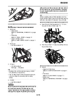
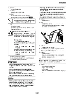
c. Check the thickness of the current valve
pad.
TIP
The thickness “a” of each valve pad is marked
in hundredths of millimeters on the side that
touches the valve lifter.
Example:
If the valve pad is marked “155”, the pad
thickness is 1.55 mm (0.061 in).
d. Calculate the sum of the values obtained in
steps (b) and (c) to determine the required
valve pad thickness and the valve pad
number.
Example:
1.55 mm (0.061 in) + 0.03 mm (0.001 in) =
1.58 mm (0.062 in)
The valve pad number is 158.
e. Round off the valve pad number according
to the following table, and then select the
suitable valve pad.
TIP
Refer to the following table for the available
valve pads.
Example:
Valve pad number = 158
Rounded value = 160
New valve pad number = 160
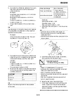
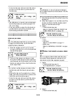
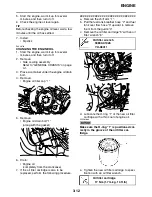
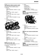
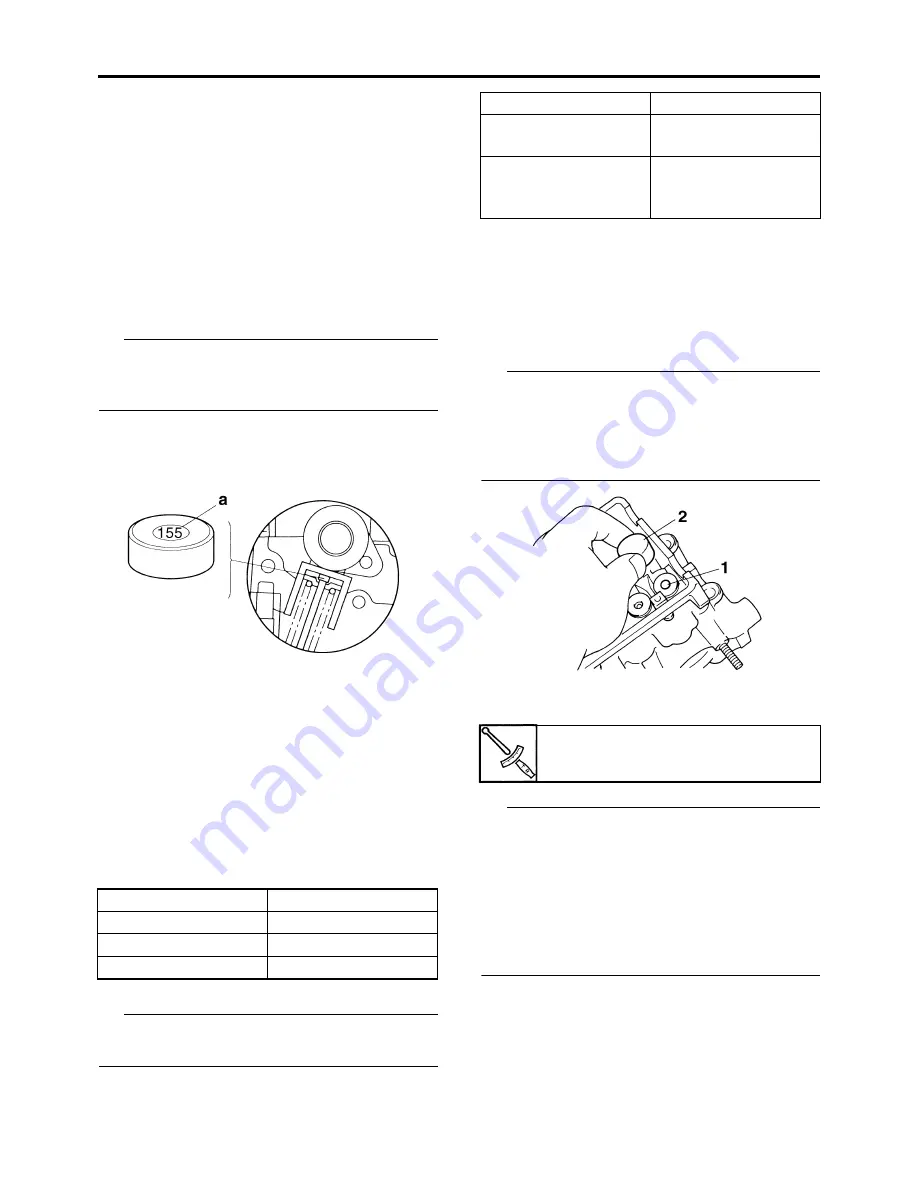
f.
Install the new valve pad “1” and the valve
lifter “2”.
TIP
• Lubricate the valve lifter with engine oil.
• The valve lifter must turn smoothly when
rotated by hand.
• Install the valve lifter and the valve pad in the
correct place.
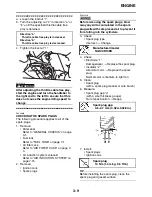
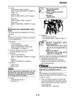
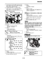
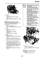
g. Install the exhaust and intake camshafts,
timing chain and camshaft caps.
TIP
• Refer to “CAMSHAFTS” on page 5-7.
• Lubricate the camshaft bearings, camshaft
lobes and camshaft journals.
• First, install the exhaust camshaft.
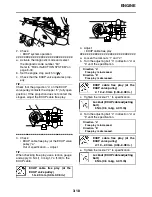
• Align the camshaft marks with the camshaft
cap marks.
• Turn the crankshaft clockwise several full
turns to seat the parts.
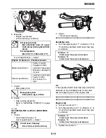
h. Measure the valve clearance again.
i.
If the valve clearance is still out of specifi-
cation, repeat all of the valve clearance
adjustment steps until the specified clear-
ance is obtained.
▲▲▲▲▲▲▲▲▲▲▲▲▲▲▲▲▲▲▲▲▲▲▲▲▲▲▲▲▲▲
Last digit
Rounded value
0, 1, 2
0
3, 4, 5, 6
5
7, 8, 9
10
Valve pad range
Nos. 150–240
Valve pad thickness
1.50–2.40 mm
(0.0591–0.0945 in)
Available valve pads
25 thicknesses in
0.05 mm (0.002 in)
increments
Camshaft cap bolt
10 Nm (1.0 m·kg, 7.4 ft·lb)
Summary of Contents for R6 2009
Page 1: ...SERVICE MANUAL YZFR6Y C 13S 28197 11 LIT 11616 22 51 2009 ...
Page 6: ......
Page 8: ......
Page 60: ...LUBRICATION SYSTEM CHART AND DIAGRAMS 2 29 EAS20410 LUBRICATION DIAGRAMS 1 2 3 4 ...
Page 62: ...LUBRICATION SYSTEM CHART AND DIAGRAMS 2 31 1 2 3 4 8 7 6 5 ...
Page 64: ...LUBRICATION SYSTEM CHART AND DIAGRAMS 2 33 1 2 3 4 5 ...
Page 66: ...LUBRICATION SYSTEM CHART AND DIAGRAMS 2 35 1 5 4 3 2 ...
Page 68: ...LUBRICATION SYSTEM CHART AND DIAGRAMS 2 37 3 1 2 5 4 ...
Page 70: ...LUBRICATION SYSTEM CHART AND DIAGRAMS 2 39 1 3 2 ...
Page 71: ...LUBRICATION SYSTEM CHART AND DIAGRAMS 2 40 1 Oil pipe 2 Main axle 3 Drive axle ...
Page 72: ...COOLING SYSTEM DIAGRAMS 2 41 EAS20420 COOLING SYSTEM DIAGRAMS 1 2 3 4 ...
Page 74: ...COOLING SYSTEM DIAGRAMS 2 43 A A 2 1 3 4 5 6 7 8 6 13 8 9 15 14 9 10 11 12 ...
Page 76: ...CABLE ROUTING 2 45 EAS20430 CABLE ROUTING ...
Page 78: ...CABLE ROUTING 2 47 ...
Page 80: ...CABLE ROUTING 2 49 ...
Page 82: ...CABLE ROUTING 2 51 ...
Page 84: ...CABLE ROUTING 2 53 ...
Page 86: ...CABLE ROUTING 2 55 ...
Page 88: ...CABLE ROUTING 2 57 ...
Page 90: ...CABLE ROUTING 2 59 A A ...
Page 92: ...CABLE ROUTING 2 61 ...
Page 95: ......
Page 135: ......
Page 206: ...CHAIN DRIVE 4 71 1 2 3 a a New ...
Page 209: ......
Page 240: ...PICKUP ROTOR 5 31 ...
Page 286: ...TRANSMISSION 5 77 ...
Page 300: ...WATER PUMP 6 13 ...
Page 316: ...AIR INDUCTION SYSTEM 7 15 EAS27040 AIR INDUCTION SYSTEM 2 1 2 4 3 4 3 6 4 5 A A ...
Page 323: ......
Page 324: ...IGNITION SYSTEM 8 1 EAS27090 IGNITION SYSTEM EAS27110 CIRCUIT DIAGRAM ...
Page 330: ...ELECTRIC STARTING SYSTEM 8 7 EAS27160 ELECTRIC STARTING SYSTEM EAS27170 CIRCUIT DIAGRAM ...
Page 336: ...CHARGING SYSTEM 8 13 EAS27200 CHARGING SYSTEM EAS27210 CIRCUIT DIAGRAM ...
Page 339: ...CHARGING SYSTEM 8 16 ...
Page 340: ...LIGHTING SYSTEM 8 17 EAS27240 LIGHTING SYSTEM EAS27250 CIRCUIT DIAGRAM ...
Page 344: ...SIGNALING SYSTEM 8 21 EAS27270 SIGNALING SYSTEM EAS27280 CIRCUIT DIAGRAM ...
Page 351: ...SIGNALING SYSTEM 8 28 ...
Page 352: ...COOLING SYSTEM 8 29 EAS27300 COOLING SYSTEM EAS27310 CIRCUIT DIAGRAM ...
Page 355: ...COOLING SYSTEM 8 32 ...
Page 356: ...FUEL INJECTION SYSTEM 8 33 EAS27330 FUEL INJECTION SYSTEM EAS27340 CIRCUIT DIAGRAM ...
Page 395: ...FUEL INJECTION SYSTEM 8 72 ...
Page 396: ...FUEL PUMP SYSTEM 8 73 EAS27550 FUEL PUMP SYSTEM EAS27560 CIRCUIT DIAGRAM ...
Page 399: ...FUEL PUMP SYSTEM 8 76 ...
Page 400: ...ELECTRICAL COMPONENTS 8 77 EAS27970 ELECTRICAL COMPONENTS ...
Page 402: ...ELECTRICAL COMPONENTS 8 79 1 5 4 3 2 6 7 8 9 10 12 13 11 14 15 16 17 18 ...
Page 404: ...ELECTRICAL COMPONENTS 8 81 EAS27980 CHECKING THE SWITCHES ...
Page 431: ......
Page 432: ...YAMAHA MOTOR CO LTD 2500 SHINGAI IWATA SHIZUOKA JAPAN ...


