Yamaha QL5 Reference Manual Download Page 70

Channel Job

 Reference Manual

70

Linking the desired input channels

This section explains how to link specific parameters of input channels.

NOTE

Channel link settings are saved as part of the scene.

NOTE

• You can also access the CH LINK MODE window by simultaneously pressing and then releasing 

the [SEL] keys of two or more channels that will be linked.

• When you press the [SEL] key for a channel (that belongs to a link group) to make it light, the 

[SEL] keys of all channels that belong to the same link group will blink.

• If you link an input channel to a ST IN channel, parameters that do not exist for a ST IN channel 

will be ignored.

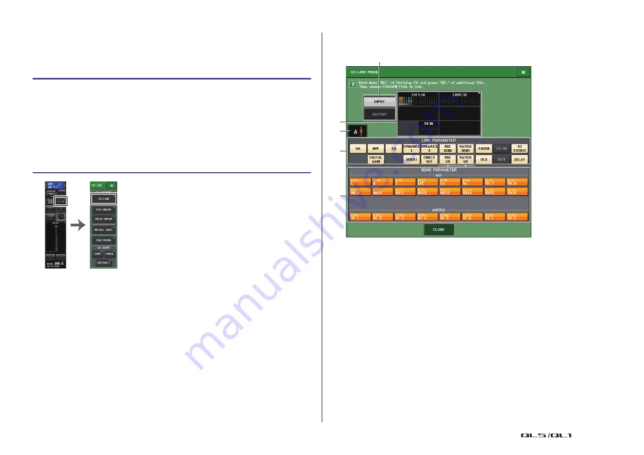
CH LINK MODE window (input channels)

You can view the channels that are linked and specify the parameters that will be linked.

1

Input channel display field

When you create a link group, the corresponding input channels will be highlighted. If 
there are two or more link groups, each group is shown in a different color. Press this 
field to open the CH LINK SET window. You can also link input channels in this window.

NOTE

• Left and right of the ST IN channel are always linked.
• In the case of the QL1, faders that do not exist on the model will not be shown.

2

Link indicator

If an input channel belonging to a link group is selected, the associated link group is 
shown. The LINK PARAMETER field and SEND PARAMETER field show the link settings.
While you hold down the [SEL] key of an input channel that does not belong to any link 
group, the link indicator shows the link group that will be created next. The LINK 
PARAMETER field and SEND PARAMETER field show the settings of the link group that 
had been previously displayed.

STEP

1.

In the Function Access Area, press the CH JOB button.

2.

Press the CH LINK button in the CH JOB menu.

3.

To link channels, hold down the [SEL] key for the link-source input channel and press 
the [SEL] key for the link-destination channel.

4.

Use the buttons of the LINK PARAMETER field in the CH LINK MODE window to 
select the parameter(s) that will be linked (multiple selections are allowed).

5.

If you turned on the MIX ON, MIX SEND, MATRIX ON, or MATRIX SEND buttons in 
step 4, use the buttons of the SEND PARAMETER field to specify the bus(es) for 
which you want operations to be linked (multiple selections are allowed).

Function 

Access Area

CH JOB 

menu

5

2

3

1

4

Summary of Contents for QL5

Page 1: ...d press the Enter key of your computer keyboard to search for occurrences of that term Displaying the next previous view If you re using Adobe Reader you can jump to the previous next view in your vie...

Page 2: ...to MATRIX buses 49 Correcting delay between channels Output Delay 51 Using the PORT TO PORT function 52 Channel library operations 53 EQ and Dynamics 54 Using EQ 54 Using dynamics 57 Using the EQ or D...

Page 3: ...NED knobs 199 Functions that can be assigned to USER DEFINED knobs 200 Custom fader bank 202 Console Lock 203 Saving and loading setup data to and from a USB flash drive 204 Word clock and slot settin...

Page 4: ...o5043 U76 Opt 2A EQ 1A DynamicEQ LIBRARY 148 DANTE INPUT PATCH LIBRARY 150 RACK VIRTUAL RACK 119 RACK MOUNTER 122 GEQ EDIT 123 GEQ LINK 124 EFFECT RACK 134 EFFECT EDIT 134 EFFECT TYPE 135 PREMIUM RACK...

Page 5: ...ENE SCENE LIST 81 GLOBAL PASTE 87 FADE TIME 91 SONG SELECT 94 FOCUS RECALL 89 PREVIEW 94 RECORDER USB 169 NUENDO LIVE 178 CH JOB CH LINK MODE 70 DCA GROUP ASSIGN 62 MUTE GROUP ASSIGN 64 RECALL SAFE MO...

Page 6: ...on the option POPUP APPEARS WHEN KNOB S PRESSED on the PREFERENCE tab accessed by pressing the SETUP button then the USER SETUP button pressing a knob repeatedly will open or close the screen 1ch Even...

Page 7: ...the send point will be fixed at POST FADER For details see Basic settings for MIX buses and MATRIX buses on page 216 Press the SEND knob or PAN knob on screen to open the SEND 8ch window GAIN PATCH fi...

Page 8: ...s of a signal sent from the channel to the STEREO MONO bus If an INPUT MIX channel is set to LCR mode the LCR button appears in location 2 The LCR button is an overall on off switch for the signals se...

Page 9: ...LPF you can switch LPF on or off using the HIGH band GAIN knob on the panel If the LOW band filter type is set to HPF you can switch HPF on or off using the LOW band GAIN knob on the panel EQ graph fi...

Page 10: ...el setting by numerical value If the signal is clipping at any point in the channel the CLIP indicator will light 3 ON button Switches the channel on or off The button is linked with the corresponding...

Page 11: ...network If the GAIN knob has been assigned to the TOUCH AND TURN knob press the knob to open the GAIN PATCH 8ch window 2 OVER indicator Lights when a signal at the input port or from the rack output...

Page 12: ...e HPF EQ 1ch window in which you can set the HPF and EQ NOTE If DCA or monitor has been selected this field will be blank DYNAMICS 1 2 field This field displays the threshold value and meter for Dynam...

Page 13: ...the signal is mono and the BALANCE knob will appear if the signal is stereo 2 ST MONO indicator Indicates the status of a signal sent to the STEREO MONO bus If an input or MIX channel is set to LCR mo...

Page 14: ...ndow to patch QL console s output channels and Dante audio network In this window assign output channel signals to DANTE 1 64 ports for QL5 or DANTE 1 32 ports for QL1 Next patch the output signals fr...

Page 15: ...the corresponding channel When you press this button a screen will appear in which you can select an icon or sample name 3 Channel name input box Indicates the name that is assigned to the correspondi...

Page 16: ...ou can either select the output port that will be the output destination of each output channel or you can select the output channel that will be the output source for each output port Selecting the o...

Page 17: ...gory select list Select the type of port 7 Port select buttons From the category these buttons let you select the port to patch To cancel the selection press the button once again 8 Tabs Enable you to...

Page 18: ...CUE STEREO L STEREO R MONO C CUE L CUE R NOTE In the case of QL1 channels that do not exist on the model will not be shown 2 Channel select button Select the channel to be assigned to the output port...

Page 19: ...OUTPUT button output channels only Specifies whether the insert point setting will be applied to all output channels NOTE Insert 1 and insert 2 are serial connections with fixed sequential numbers IN...

Page 20: ...ategory of port The categories correspond to the following ports The displayed categories vary depending on the channel type DANTE1 32 DANTE1 DANTE32 DANTE33 64 DANTE33 DANTE64 QL5 only INPUT INPUT1 3...

Page 21: ...PATCH button Displays the currently selected Direct Out output port Press this button to open the PORT SELECT window in which you can select an output port 3 DIRECT OUT ON button Switches the Direct O...

Page 22: ...ORT SELECT window Displayed when you press the DIRECT OUT PATCH button in the one channel or the eight channel INSERT DIRECT OUT window Set the output port used for direct output 1 Category select lis...

Page 23: ...This is an on off switch for signals sent from the input channel to MIX buses 1 16 MIX LEVEL 1 16 MIX send levels 1 16 Adjusts the send level of signals sent from the input channel to VARI type MIX b...

Page 24: ...lains how to specify the channel name icon and channel color PATCH NAME screen When selecting the PATCH tab 1 PATCH button Indicates the currently patched port If you press this button when another ta...

Page 25: ...can also add or edit characters in the channel name field after you have entered the sample name If you want to quickly assign channel names that consist of a common name plus a consecutive number suc...

Page 26: ...the head amp You can use the TOUCH AND TURN knob to adjust the gain If the Gain Compensation function is turned on an indicator will appear showing the position of the analog gain when the function i...

Page 27: ...AIN digital gain knob Indicates the digital gain value You can use the TOUCH AND TURN knob to adjust the digital gain If the Gain Compensation function is turned on no changes will be made to the inpu...

Page 28: ...witch phantom power 48V on or off A GAIN analog gain knob Indicates the analog gain of the head amp You can use the TOUCH AND TURN knob to adjust the gain If the Gain Compensation function is turned o...

Page 29: ...l This indicator is available only if an input channel is selected 3 48V indicator Indicates the 48V on off status for each channel 4 Phase indicator Indicates the phase setting for each channel NOTE...

Page 30: ...perform this operation rapidly if you ve assigned Gain Compensation on off as the SET BY SEL function to one of the USER DEFINED keys Sending the signal from an input channel to the STEREO MONO bus Th...

Page 31: ...screen and then press the knob once again 4 Use the MODE select button in the TO STEREO MONO window to select either ST MONO mode or LCR mode for each channel 5 In the MASTER section on the top panel...

Page 32: ...ess the knob to select it and then operate the TOUCH AND TURN knob page 33 TO STEREO MONO window CH1 32 CH33 64 ST IN QL5 ST IN QL1 Adjusts the status of a signal sent from the corresponding input cha...

Page 33: ...When the CSR knob is set to 100 ST IN channel C L R TO ST PAN knob Signal sent to the STEREO L bus Signal sent to the STEREO R bus Signal level C L R TO ST BALANCE knob Signal sent from the STEREO L...

Page 34: ...nels to a specific MIX MATRIX bus can be adjusted simultaneously Using the SELECTED CHANNEL section This section explains how to use the TOUCH AND TURN knob to adjust the send levels of signals sent f...

Page 35: ...s the send point to PRE The send point is the point at which signals are sent from all send source channels including the input and output channels to the selected send destination At this time the PR...

Page 36: ...n to a USER DEFINED key This lets you quickly switch to SENDS ON FADER mode for a specific MIX MATRIX bus and quickly switch back again SENDS ON FADER mode 1 MIX MATRIX select button Use the MIX MATRI...

Page 37: ...INPUT DELAY window 8ch You can set the on off status and the value of the input channel delay 1 DELAY SCALE button Press the button to display the DELAY SCALE window in which you can select the unit f...

Page 38: ...can select the unit for the delay time 2 Channel select button Lights to indicate the currently selected input channel Press the button to select the channel 3 Delay setting knob input channels only U...

Page 39: ...hown below 1 LR MONO SELECT field Select one of the four buttons The button you select lights up and the others go off If a stereo input channel is selected the OVERVIEW screen will appear as shown be...

Page 40: ...ition Use the SEND knob MIX 3 of the Selected Channel section to make adjustments 3 Assign buttons for each bus If there is a bus from which you do not want to output an audio signal turn that button...

Page 41: ...the surround positions Press here to open the SURROUND PAN 1CH screen OVERVIEW screen If you set a bus to Surround mode in BUS SETUP the OVERVIEW screen appears as shown below 1 Surround graph This gr...

Page 42: ...eter is used to set the front rear surround position You can use the TOUCH AND TURN knob to adjust this 6 DIV knob This determines how the Center signal is fed to the Left Right and Center channels Wh...

Page 43: ...own below This screen is displayed when you press the pan display area in the SELECTED CHANNEL VIEW screen or the OVERVIEW screen 1 Surround graph This graph shows the surround positions 2 L R F R swi...

Page 44: ...p indicator The TO STEREO MONO OUTPUT screen appears as shown below Parameters cannot be set for MIX 1 6 this screen is only for displaying parameters Channel library operations Channel libraries incl...

Page 45: ...NSERT 1 2 OUT To OUTPUT PATCH MIX INSERT 1 2 IN 1 16 To RACKIN PATCH MIX INSERT 1 2 OUT 1 16 ST L MONO C ST R PAN BAL TO ST LR MONO TO MONO LCR TO LCR CSR POST ON PAN MODE PRE FADER POST ON PRE FADER...

Page 46: ...ATRIX buses INSERT You can patch the desired output input ports to insert an external device such as an effect processor You can switch the insert out and insert in locations METER Indicates the level...

Page 47: ...n the TO STEREO MONO window to select either ST MONO mode or LCR mode for each channel 4 In the MASTER section on the top panel turn on the ON key for the STEREO channel MONO channel and then raise th...

Page 48: ...9 CSR knob Adjusts the relative level of signals sent from the channel to the STEREO L R bus and to the MONO C bus in the range of 0 100 To adjust the value press the knob to select it and then opera...

Page 49: ...tion to access the corresponding MIX MATRIX channel and then press the appropriate CUE key in the Channel Strip section MATRIX SEND screen 1 ALL PRE button Sets the send point to PRE The send point is...

Page 50: ...levels of the signals that are routed from each channel to the currently selected MIX MATRIX bus The ON keys will also change to the SEND ON status If you press the currently selected MIX MATRIX bus s...

Page 51: ...is assigned 4 Channel select button Enables you to select the channel that you want to assign to the output port The name of the currently selected channel is displayed 5 Delay time knob Sets the dela...

Page 52: ...o use the I O jacks on QL series consoles as I O jacks for an audio network OUTPUTS PHONES OUT LR PHONES DA PHONES LEVEL 2 Tip Ring Sleeve OUTPUT PATCH OUTPUT PATCH STEREO OUT L STEREO OUT MONO C STER...

Page 53: ...the channel to be assigned to the output port from the current category 3 CLOSE button Closes the screen Channel library operations Channel libraries include OUTPUT CHANNEL LIBRARY which enables you...

Page 54: ...f a wide variety of presets suitable for various instruments or situations You can also access the SELECTED CHANNEL VIEW screen and use the knobs in the SELECTED CHANNEL section to edit the EQ and hig...

Page 55: ...ner s Manual E EQ FLAT button Press this button to reset the GAIN parameters of all EQ band to 0 dB F HIGH SHELVING ON OFF button Turn on this button to select the shelving type filter for the HIGH ba...

Page 56: ...al is clipping 4 HPF FREQUENCY knob input channels only Indicates the cutoff frequency of the HPF You can use the knobs in the SELECTED CHANNEL section to adjust this 5 HPF ON OFF button input channel...

Page 57: ...ndow 2 DEFAULT button Press this button to reset all dynamics parameters to the initial values 3 COPY button All dynamics parameter settings will be copied in buffer memory 4 PASTE button Press this b...

Page 58: ...key in signal that will trigger the dynamics SELF PRE EQ The pre EQ signal of the same channel SELF POST EQ The post EQ signal of the same channel MIX OUT 13 16 Output signals of MIX channels 13 16 CH...

Page 59: ...GATE is selected as the dynamics type the indicator status means the following 3 Dynamics graph Indicates the dynamics parameter values The currently selected dynamics type appears below the graph Pr...

Page 60: ...is an INPUT EQ LIBRARY that lets you store recall EQ settings for input channels and an OUTPUT EQ LIBRARY that lets you store and recall EQ settings for output channels To recall settings from a libr...

Page 61: ...and then specify the DCA group to which it should be assigned NOTE DCA group settings are saved as part of the scene With QL V3 0 and later you can now assign the Stereo Mono bus master Mix bus master...

Page 62: ...roup When you press this button the keyboard window will appear allowing you to enter or edit the text 5 DCA group select button Selects the DCA group that you want to assign 6 POST ONLY button Specif...

Page 63: ...ut channels Both types of channels can exist in the same group Assigning channels to mute groups As with the DCA group there are the following two ways to assign channels to mute groups You can select...

Page 64: ...te group While this window is displayed press the SEL key for the channel that you want to assign to the mute group The channel will be assigned to the mute group and the on screen fader for that chan...

Page 65: ...rol mute groups you can use the MUTE GROUP MASTER buttons in the MUTE GROUP ASSIGN window In addition it may prove convenient if you assign the Mute On Off function for a mute group 1 8 to a USER DEFI...

Page 66: ...isabling the Mute function Mute can be temporarily disabled by turning on the ON key and resumed by turning it off when you mute one of the mute groups to which that channel belongs However this mute...

Page 67: ...ion 3 SET BY SEL button Enables you to use the SEL keys on the panel to select channels that will be affected by the Recall Safe function Turn this button on and then press the SEL key for the channel...

Page 68: ...nnel STEREO channel MONO channel If Recall Safe is turned on for global parameters the safe parameter select buttons of the selected channel will light green as follows In this illustration the items...

Page 69: ...eate or on the number and combinations of channels that can be included in these link groups You can select the types of parameters to be linked for each link group However input channels and output c...

Page 70: ...t and right of the ST IN channel are always linked In the case of the QL1 faders that do not exist on the model will not be shown 2 Link indicator If an input channel belonging to a link group is sele...

Page 71: ...link group Adding a new channel to an existing link group Hold down any SEL key within the group and press the SEL key that you want to add to the group NOTE If the link destination channel is alread...

Page 72: ...parameters you can select in the LINK PARAMETER field 1 MATRIX channel not applicable NOTE If you link Dynamics for two or more output channels the parameter values will be linked but the key in sour...

Page 73: ...d linked channel adjust the parameter value You can also remove all linked channels from the same link group temporarily This can be helpful if you want to edit parameters that are linked to each othe...

Page 74: ...he parameters of the copy destination You can copy between the following combinations of channels Between input channels Between the STEREO L R channel and MONO channel Between MIX channels Between MA...

Page 75: ...he selected copy destination channels press the DESTINATION CHs field NOTE In the case of the QL1 faders that do not exist on the model will not be shown 3 COPY button Executes the copy operation Afte...

Page 76: ...that do not exist on the model will not be shown 3 MOVE button Executes a move operation After selecting the move source channel and move destination channel the channel settings move from the move so...

Page 77: ...als sent to the MIX MATRIX buses You can use this function to quickly send monitoring signals to a performer or announcer simply by removing his or her audio signal NOTE This Mix Minus function is a s...

Page 78: ...Channel Job Reference Manual 78 NOTE You can also access the MIX MINUS popup window by pressing the CH JOB button in the Function Access Area then pressing the MIX MINUS button...

Page 79: ...tings Mute group settings Channel link settings Panel assignment status PANEL SNAPSHOT CUSTOM FADER BANK settings The number of the currently selected scene appears in the SCENE field of the Function...

Page 80: ...CENE TITLE field Press this field to select it and then enter a title for the scene maximum 16 characters 2 COMMENT field Press this field to select it and then enter a comment for the scene You can u...

Page 81: ...with consecutive scene numbers starting with scene 001 No symbol No scene will be protected NOTE The R symbol for scene number 000 cannot be disabled 6 Current scene The currently selected scene that...

Page 82: ...processing of the current scene Recalling a scene SCENE LIST window 1 RECALL SCENE button Recalls the currently selected scene 2 RECALL UNDO button Undoes the Recall operation This button is valid on...

Page 83: ...scene number that you assigned to the USER DEFINED key When you press a USER DEFINED key to which this function is assigned the assigned scene will be recalled immediately STEP 1 In the Function Acce...

Page 84: ...ress this field to open the SCENE COMMENT EDIT window in which you can enter comments for the scene You can edit comments in this window 5 STATUS field Indicators in this field indicate the setting st...

Page 85: ...ut another scene before you paste the newly copied or cut scene will overwrite the scene in the buffer memory You cannot select multiple scenes as the copy source You can select multiple paste destina...

Page 86: ...multiple scenes that have already been stored NOTE The Global Paste function will be available for a user if the SCENE LIST STORE SORT parameter is turned on in his or her user level settings NOTE A p...

Page 87: ...DIGITAL GAIN Digital gain settings for the corresponding input channel 1 3 2 EQ EQ settings DYNA1 Dynamics 1 settings including KEY IN SOURCE and KEY IN FILTER DYNA2 Dynamics 2 settings including KEY...

Page 88: ...ecall function is specified individually for each scene the Recall Safe settings are applied to all scenes NOTE The FOCUS field enables you to make settings for the Focus function The buttons in this...

Page 89: ...NG field Specifies the content that will be saved by the next scene store operation FOCUS RECALL window Sets the parameters that will be recalled 1 CLEAR ALL button SET ALL button Turns off or on all...

Page 90: ...S RECALL Settings for DCA 1 16 are made simultaneously DCA ASSIGN button settings are linked according to the channel link for the scene 9 FOCUS button Switches the Focus Recall function on or off 0 C...

Page 91: ...lay this window press the SET button in the FADE TIME field in the SCENE LIST window 1 Channel display field The channels or DCA groups to which Fade is applied are highlighted To select the channels...

Page 92: ...ll be output from each GPI OUT Pressing a button repeatedly will switch between the following functions OFF Nothing will be output TRIGGER A trigger will be output when the scene is recalled TALLY A t...

Page 93: ...l stop when the scene is recalled regardless of the offset time setting SCENE LIST window PLAYBACK LINK field 1 PLAY button Sets the Playback Link function s on off status for each scene 2 Song select...

Page 94: ...ecalled scene will appear on the panel of the QL series console but the signal processing of the current scene will remain as it was prior to the recall Even if you modify the settings and save them a...

Page 95: ...es USER DEFINED KEYS operations USER DEFINED KNOBS operations Monitor MONITOR CUE OSCILLATOR TALKBACK changes or display Changing or viewing Nuendo Live settings Changing or viewing the recorder Chang...

Page 96: ...MONITOR MONO C MONITOR OUT MONO C MONITOR OUT R MONITOR OUT L To OUTPUT PATCH To OUTPUT PATCH To OUTPUT PATCH MONO TALKBACK ON CUE TRIM INPUT OUTPUT DCA CUE L CUE R MONO ON MONITOR LEVEL D I M M E R...

Page 97: ...urn it off if you do not want to output cue signals to the monitoring speakers Using the Monitor function This section explains how to select the desired monitor source and monitor it from the PHONES...

Page 98: ...al 4 MONITOR FADER field Enables you to set and view the monitor fader that adjusts the monitor level MONITOR FADER LEVEL knob Adjusts the monitor fader level FADER ASSIGN display This area displays t...

Page 99: ...Indicates the on off status of the dimmer function for talkback 4 PHONES LEVEL LINK button Enables you to link the signal level at the PHONES Out jack to the monitor signal level If this button is on...

Page 100: ...and R and monitor through two speakers If you have not specified an output port for MONITOR OUT C selecting the MONO C button or LCR button as the monitor source will automatically cause the MONO cha...

Page 101: ...tton Downmix in mono mode 5 Meter field Shows the meters for the surround signal being monitored The layout of the meters is the same as the layout set in the SURROUND SETUP screen SURROUND MONITOR wi...

Page 102: ...speakers When turned on all speaker buttons in the speaker mute field are turned on At this time if you press one of the speaker buttons only that button remains on the other buttons go off If you pr...

Page 103: ...nitors to the downmix parameters for the main channel MIX1 6 to STEREO Using the Cue function About CUE groups Cue signals on the QL series console can be categorized into the following four groups 1...

Page 104: ...g the Cue function This section explains how to use the CUE key for a channel or DCA group to monitor cue signals NOTE Be aware that if you turn CUE INTERRUPTION off in the MONITOR popup window the cu...

Page 105: ...the cue signal adjust the gain of the output port that is patched to it If you turn on the CUE key the cue output level is indicated The upper part of the cue meter shows an abbreviation indicating t...

Page 106: ...n enables you to make settings related to DCA cue 4 Cue point select button Sets the cue point for the DCA group to PRE PAN immediately before PAN or POST PAN immediately after PAN 5 DCA TRIM knob Ind...

Page 107: ...exceeds the value set with this knob the cue is released MONITOR screen CUE field in Surround mode If you set a bus to Surround mode in BUS SETUP the CUE field in the MONITOR screen appears as shown...

Page 108: ...you can select either a Latch operation or an Unlatch operation the function will be enabled only while you continue holding down the key page 194 When talkback is on you can use the talkback dimmer t...

Page 109: ...en the TALKBACK popup window In this popup window you can make detailed settings for talkback 1 INPUT TO TALKBACK field This field allows a mic connected to a conventional input port to be used as a t...

Page 110: ...If you press the LEVEL knob you can use the TOUCH AND TURN knob to adjust the oscillator level 3 OSCILLATOR MODE field Indicates the currently selected oscillator mode Pressing the MODE button repeat...

Page 111: ...u can adjust the value by using the TOUCH AND TURN knob LEVEL knob EVEN R Indicates the output level of the sine wave on the EVEN R side You can adjust the value by using the TOUCH AND TURN knob FREQ...

Page 112: ...he ASSIGNED indicator is lit green for a tab that contains a selection If the mode is set to SINE WAVE 2CH the signal is output to either odd ODD L side or even EVEN R side of the selected channel For...

Page 113: ...points the points in the signal route at which the level is detected To access the METER screen press the METER field of the Function Access Area INPUT OUTPUT RTA tab Use these tabs to switch between...

Page 114: ...t channels For INPUT METER PRE GC Immediately before GAIN COMPENSATION PRE D GAIN Immediately before DIGITAL GAIN POST D GAIN Immediately after DIGITAL GAIN PRE FADER Immediately before the fader imme...

Page 115: ...bus changes color RTA METER screen This is the real time analyzer screen The results of a frequency analysis for the selected source are shown in the 1 6 octave band 61 band 1 Frequency Response grap...

Page 116: ...button Setting this switch to ON allows you to add rate of decay to the graph FAST SLOW switch button Use this button to set the rate of decay FAST SLOW 7 HOLD button Press this button to hold the gra...

Page 117: ...eter for the STEREO signal is shown on the right side The layout for L R C LFE Ls and Rs is the same as the layout set in the SURROUND SETUP screen When cue is operating EFFECT CUE is shown on the rig...

Page 118: ...will be only one channel each for input and output The figure below shows the signal flow for the virtual racks NOTE The QL console provides a rack for mounting an I O rack such as an R series externa...

Page 119: ...r the rack If this button is turned on for a rack the contents and parameters of that rack will not change when a scene is recalled For more information on Recall Safe refer to Using the Recall Safe f...

Page 120: ...In the case of the EFFECT the operation is the same as that of the GEQ if you select DYNAMICS EQ as the EFFECT TYPE In the case of the PREMIUM RACK the operation is the same as that of the GEQ For mo...

Page 121: ...ess this area to open the GEQ EDIT window in which you can modify the GEQ settings for A and B If 8BandPEQ is mounted This area indicates the EQ frequency response the PEQ on off status and the input...

Page 122: ...ove a GEQ PEQ or effect that was mounted in a rack and close the RACK MOUNTER window all edits to the parameter settings for that GEQ PEQ or effect will be discarded If you have not yet closed the win...

Page 123: ...e popup window of GEQ effect or premium rack that is inserted in that channel 1 Rack select tabs Switch among GEQ 1 8 or among EFFECT 1 8 For a rack in which a Flex15GEQ is mounted the tabs will be sp...

Page 124: ...n linked GEQ y x button The parameters of y will be copied to x and then linked RESET BOTH button The parameters of both will be initialized and then linked CANCEL button Cancels the link and closes t...

Page 125: ...rent 31BandGEQ 2 Faders Indicate the amount of boost and cut for each band of the 31BandGEQ The actual values are shown in the numerical boxes below 3 FADER ASSIGN field Use the faders in the Channel...

Page 126: ...u close the GEQ window the buttons in the FADER ASSIGN field automatically turn off GEQ EDIT window Flex 15GEQ This window is the same as that for the 31BandGEQ except that the AVAILABLE BANDS paramet...

Page 127: ...be copied in buffer memory 7 PASTE button Press this button to paste the copied settings from buffer memory to the current EQ If no valid data has been copied in the buffer memory nothing will happen...

Page 128: ...PEQ IN OUT level meters Indicate the peak level of signals before and after the PEQ C Rack select tabs Switch among GEQ 1 8 or EFFECT 1 8 For a rack in which an 8BandPEQ is mounted the tabs will be s...

Page 129: ...tiple mics freeing the engineer from making constant fader adjustments Automixer operating principle With the Dugan speech system used in Automixer you can automatically adjust the gain for multiple m...

Page 130: ...n optimum level for Automix NOTE If the level indicator flashes increase the input gain If the level indicator lights up red reduce the input gain 2 Meter indicator There are three display modes Press...

Page 131: ...ster OVERRIDE button is turned on When the master OVERRIDE button is turned off the channel will return to its previous mode The override function is convenient when the moderator of a panel discussio...

Page 132: ...a desired channel except for a ST IN channel so that the effect is inserted into that channel The internal effects fall into two categories STEREO type 2 in 2 out effects that process the L R channel...

Page 133: ...hannel you selected as the output destination for the rack to the corresponding MIX bus is set to dB If you raise this send level the output of the effect will be returned to the input of the same eff...

Page 134: ...put and output channels 1 IN 2 OUT or 2 IN 2 OUT of this effect is also shown 2 Input output meters Indicate the level of the signals before and after the effect STEP 1 Follow steps 1 3 described in V...

Page 135: ...Effect types HQ PITCH and FREEZE can be used only in rack 1 3 5 or 7 Also even if you copy these two effect types you will not be able to paste them to rack 2 4 6 or 8 4 EFFECT CUE button Cue monitors...

Page 136: ...ou can also make fine adjustments by rotating the knob while pressing and holding it down 9 MIX BAL knob Adjusts the balance between the original sound and effect sound included in the output signal f...

Page 137: ...ored If you turn on the MIDI CLK button in the special parameter field the BPM parameter value will change in relation to the tempo of the MIDI timing clock received from the MIDI port USER SETUP wind...

Page 138: ...AY NOTE x 4 x 60 TEMPO sec FREQ TEMPO 60 NOTE x 4 Hz Example 1 When SYNC ON DELAY 250 ms TEMPO 120 you change NOTE from 8th note to quarter note DELAY new NOTE x 4 x 60 TEMPO 1 4 x 4 x 60 120 0 5 sec...

Page 139: ...also recall the FREEZE effect type from the effect library Using the Premium Rack The QL series console features processors that faithfully emulate meticulously selected vintage analog processors and...

Page 140: ...rack space If you mount a two space Premium Rack processor in the rack you will be unable to mount any more processors below those rack spaces Also you cannot mount a two space processor in an even nu...

Page 141: ...esigns RND 5033EQ features a unique tone control response It inherited the history of the 1073 which was praised as one of the greatest devices developed by Mr Rupert Neve Yamaha s VCM technology has...

Page 142: ...e compressor is bypassed the button indicator will turn off However even if the compressor is bypassed the signal will pass through the input output transformer and amp circuits 2 INPUT meter Indicate...

Page 143: ...tially distorted aggressive sound 5 METER switch buttons Switch the meter display GR Indicates the amount of gain reduction applied by the compressor 4 8 Each meter uses 18 dB as the reference level o...

Page 144: ...el will decrease This affects only the response of the boost 6 HIGH FREQUENCY knob Sets the frequency of the high range filter This affects only the response of the boost 7 HIGH BOOST knob Sets the am...

Page 145: ...t signal Rotating the knob clockwise will set the ratio for boost and counter clockwise for cut Fully rotating the knob in either direction will create the maximum effect 9 ATTACK RELEASE buttons Enab...

Page 146: ...5dB the input gain is 5dB and the output gain is 5dB See below for more information about how to use INPUT ADJUST If the level of the input signal sent to effects is too low to reach the threshold inc...

Page 147: ...hes as follows VU GR VU When METER is IN When METER is GR When METER is OUT 9 VU SELECT DUAL mounting Selects the signal source for the VU meter You can select from input level or output level 0 LIMIT...

Page 148: ...r one rack you can store and recall two Flex15GEQ or 8BandPEQ units independently as A and B To access the GEQ EDIT window or the PEQ EDIT window press the rack container in the GEQ field Effect libra...

Page 149: ...g to different DEVICE TYPEs but share the same ID a red CONFLICT indicator will appear to the left below the device If multiple devices share the same ID a yellow DUPLICATE indicator will appear to th...

Page 150: ...to execute auto patching Otherwise press CANCEL to return to the previous screen 3 Port select buttons Press to display the PORT SELECT window Dante Device ID number hexadecimal and channel number dec...

Page 151: ...display the I O DEVICE screen I O page 2 Press the rack in which the I O device that has head amp functionality is mounted 3 Open the I O DEVICE HA screen to remotely control the head amp of the I O d...

Page 152: ...is shows the HA settings of the I O device Press this area to open the I O DEVICE HA window in which you can make detailed head amp settings If you press the SEL key of an input channel the correspond...

Page 153: ...selected the unit automatically detects the frame frequency 48 kHz 96 kHz of the MADI input signal 5 MADI STATUS INPUT status MADI STATUS OUTPUT status Display information regarding the MADI input and...

Page 154: ...se controllers switch on or off the high pass filter built into the head amp of the I O device and adjust its cutoff frequency If you press and select the FREQUENCY knob you can make adjustments using...

Page 155: ...ling WIRELESS unit This section explains how to remotely control a WIRELESS unit that s connected to the Dante connector I O DEVICE screen WIRELESS page 1 Display switch buttons Press one of these but...

Page 156: ...AD8HR from the QL series console To transmit audio signals input to the AD8HR to the QL series console connect the DIGITAL OUT A or B connector on the AD8HR to the AES EBU connector on the NAI48 ES us...

Page 157: ...can use a daisy chain or ring connection and install one MY16 EX expansion card in the slot on the QL unit to remotely control up to two SB168 ES units simultaneously NOTE Remote control data will be...

Page 158: ...pen the EXTERNAL HA window for that rack 4 EXTERNAL HA PORT SELECT button Press this button to display the HA PORT SELECT window in which you can set the input port for the external head amp mounted i...

Page 159: ...external HA unit itself 2 48V button These switch phantom power on off for each channel 3 GAIN knob These indicate the gain of the external HA If you press and select the GAIN knob you can make adjust...

Page 160: ...level meter located at the immediate right of the knob indicates the input level for the corresponding port 4 GC button Switches on or off the Gain Compensation function that maintains a consistent s...

Page 161: ...can be executed when Parameter Changes are received from an external device Using this capability QL operations can be recorded and played back on a MIDI sequencer or other external device In additio...

Page 162: ...eceived in Single mode Multi mode transmission reception and Single mode transmission are disabled BANK If this button is on Bank Select messages can be transmitted and received in Single mode Bank Se...

Page 163: ...ill vary depending on the card that is installed The currently available card is valid only for port 1 3 OK button Confirms the settings and closes the window MIDI SETUP window for channel selection T...

Page 164: ...the PROGRAM CHANGE section of the MIDI SETUP page Tx If this is on the corresponding Program Change messages will be transmitted when events on the list are executed Rx If this is on the corresponding...

Page 165: ...n 128 events on a single MIDI channel When Bank Select and then Program Change messages in that order are received on the Rx channel the event assigned to that bank number and program number in the li...

Page 166: ...control number Using NRPN Non Registered Parameter Number This method uses a special type of Control Change messages called NRPN NRPN uses Control Change numbers 99 and 98 to specify the MSB Most Sig...

Page 167: ...single MIDI channel as NRPN messages If you select this mode the assignments in the list will be ignored TABLE mode when the TABLE button is on Various mix parameters on the QL series console will be...

Page 168: ...ions ON key on off operations system and user settings etc as an alternative to using Control Changes or NRPN messages For details on the Parameter Changes that can be transmitted and received refer t...

Page 169: ...der output to any desired input channel NOTE The USB memory recorder always records and plays back in stereo If you want to record in monaural with the same signal for left and right you must assign b...

Page 170: ...t to the recorder 7 PLAYBACK OUTPUT CUE button Press this button to monitor the signal output from the recorder NOTE You cannot turn on this button and the RECORDER INPUT CUE button simultaneously 8 M...

Page 171: ...PORT field This field enables you to control recording and playback of a song 1 Current song Indicates the currently selected song s track number title and artist name The following indicators will ap...

Page 172: ...anges the recorder mode as follows Stop mode Playback mode then starts playback from the beginning of the current song Playback mode Playback pause mode Playback pause mode Playback mode then starts p...

Page 173: ...from the sampling rate of the audio file being played the SRC Sampling Rate Converter function will automatically convert the rate so that the file will be played back correctly If the REPEAT button i...

Page 174: ...d with a PLAY check symbol If this button is off the recorder will stop after playback of the current song is complete unless there are no subsequent songs that are marked with a PLAY check symbol One...

Page 175: ...AW software such as Steinberg Nuendo to an audio network that includes a QL console you must use Dante Virtual Soundcard DVS software DVS works as an audio interface making it possible to transmit sig...

Page 176: ...Dante latency Use a high setting to ensure stability when using multiple channels In the Advanced settings select the number of channels to be used for recording and playback the default is 8 x 8 NOT...

Page 177: ...te Virtual Sound Card ASIO Dante for Mac or Yamaha AIC128 D as the sound card or audio driver used for input output Some DAW software may require internal patching for the driver and the DAW software...

Page 178: ...s of Nuendo Live 2 PEAK CLEAR button Clears the peak levels indicated by the peak hold function 3 Marker list field Lists the marker information recorded in the current Nuendo Live project The markers...

Page 179: ...recording from being accidentally stopped during recording G DVS information display Shows the device label of the selected DVS H ADD MARKER button Adds a marker to the project at the current location...

Page 180: ...hen setup method selection button SPECIFIED IP ADDRESS When using Dante Accelerator specify the IP address of the computer in the SPECIFIED IP ADDRESS field Since the IP address of Dante Accelerator w...

Page 181: ...press the PORT SELECT button for the port to which you want to assign the signal from Nuendo Live 3 In the list at the left of the PORT SELECT window select the DVS you re using with Nuendo Live and s...

Page 182: ...thentication key 7 SAVE LOAD button Press this button to open the SAVE LOAD window in which you can save or load user authentication keys and console files SYSTEM SETUP field This field enables you to...

Page 183: ...ll be grayed out If you press the 5 1 SURROUND button to switch to Surround mode you can then set the bus settings for MIX1 6 Assign channels to MIX 1 6 for surround output You can press the APPLY but...

Page 184: ...OLE LOCK button This button executes the Console Lock function If the console password has been set pressing this button will open the AUTHORIZATION window Enter the correct password to execute Consol...

Page 185: ...of functionality permitted by the Administrator Only one set of Guest settings is maintained inside the console User A User can use only the range of functionality permitted by the Administrator User...

Page 186: ...he file name of the user authentication key will be the current user name and it will be created and saved in the root directory STEP 1 In the Function Access Area press the SETUP button 2 In the SETU...

Page 187: ...as a User you must either select a key that is saved in the console itself or connect the USB flash drive in which a user authentication key has been saved If you use a user authentication key on a U...

Page 188: ...CURRENT USER button 3 In the LOGIN window press the GUEST button and then press the LOGIN button STEP 1 In the Function Access Area press the SETUP button 2 In the SETUP screen press the CURRENT USER...

Page 189: ...user you can edit your preference settings USER DEFINED keys USER DEFINED knobs custom fader banks master fader comments and password and save overwrite them onto your user authentication key If you a...

Page 190: ...channel for which you want to make settings The type of buttons shown will depend on the selected channel or group INPUT channel HA PROCESSING FADER ON MIX MATRIX channel WITH SEND PROCESSING FADER O...

Page 191: ...SORT operations RECALL operations 4 LIBRARY LIST Specifies the operations that can be performed on libraries STORE CLEAR operations RECALL operations 5 FILE LOAD Specifies the settings that will be ap...

Page 192: ...does not select the Help language 4 ERROR MESSAGE field Specifies whether error messages will be displayed DIGITAL I O ERROR If this is on an error message will appear when a digital audio I O error...

Page 193: ...he SCENE windows When the SCENE 1 1 button is lit pressing the USER DEFINED key assigned to INC RECALL or DEC RECALL will increment or decrement the scene number When the LIST UP DOWN button is lit pr...

Page 194: ...as been assigned the key will light The Alternate function features two options LATCH and UNLATCH UNLATCH Alternate mode is turned on only while you are pressing and holding down the USER DEFINED key...

Page 195: ...with the button turned off group b PRESET ON Switch the channels in group b to the mode indicated by the mode button man auto mute next to the lit preset indicator group c OVERRIDE ON Apply a fade in...

Page 196: ...ECALL EFFECT BYPASS EFFECT RACK1 8 PREMIUM RACK1A PREMIUM RACK1B PREMIUM RACK8A PREMIUM RACK8B FADER BANK SNAPSHOT Takes a snapshot of the bank settings hold down the key for two seconds or longer or...

Page 197: ...C Ls Rs LFE This functionality is the same as the SPEAKER MUTE function in the SURROUND MONITOR screen When the SOLO button is on it functions as a SOLO key FUNCTION PARAMETER 1 PARAMETER 2 Explanati...

Page 198: ...ONO SET TO LCR SET GAIN COMPENSATION SET AUTOMIXER AUTO MAN SET DEFAULT VALUE While holding down this key press SELECTED CH or the TOUCH AND TURN knob to reset it to the default value It goes OFF when...

Page 199: ...channel is assigned and TALKBACK is ON at the same time the LED will be on Otherwise the LED will be off TAP TEMPO CURRENT PAGE Use the tap tempo function in the displayed screen EFFECT RACK1 8 WITH...

Page 200: ...nothing will occur when the key is operated About TOUCH AND TURN You can press a desired knob in the touch screen and then use the TOUCH AND TURN knob to immediately operate that on screen knob At th...

Page 201: ...ayed b If there are no parameters is displayed EQ HIGH MID Q 2 HIGH MID FREQUENCY HIGH MID GAIN HIGH Q HIGH FREQUENCY HIGH GAIN EXTERNAL HA GAIN1 GAIN8 10 HPF FREQUENCY 4 I O DEVICE GAIN1 GAIN32 11 IN...

Page 202: ...elect button Selects the target fader Press this button to select it then press SEL keys on the top panel to add the corresponding channels to the selected fader bank 4 Fader assign select button Open...

Page 203: ...ne are called up If you load ALL data that was saved in CL V1 70 or earlier since scenes do not include custom fader bank settings the custom fader bank settings for the current scene when the load wa...

Page 204: ...ator is shown in the Function Access Area while data is being accessed saved loaded or deleted During this time do not disconnect the USB port or power off the QL unit Doing so may damage the data in...

Page 205: ...ing order will alternate between ascending and descending order FILE NAME Indicates the file name or directory name and shows an icon indicating its type COMMENT The comment added to the QL console se...

Page 206: ...UT tab The following table lists the items that you can select EFFECT GEQ tab The following table lists the items that you can select PREMIUM tab The following table lists the items that you can selec...

Page 207: ...ell as settings files NOTICE Some data may contain settings that will cause the console to output signals immediately after the data is loaded Before you load turn off the power of the equipment conne...

Page 208: ...revent this load and then recall the scene that contains input output patching for the channel assignment Button Data content IN CH LIB Input channel library OUT CH LIB Output channel library IN EQ LI...

Page 209: ...ing to the column heading you press 1 FILE NAME Sort the list in numerical alphabetical order of the file names 2 COMMENT Sort the list in numerical alphabetical order of the comment 3 READ ONLY Sort...

Page 210: ...button in the SAVE LOAD window 2 Press the directory icon or press the arrow button in the PATH field to move to the directory into which you want to paste the file 3 Press the PASTE button 4 Enter t...

Page 211: ...or received correctly and noise may be present in the signal even if the sampling rates are the same Specifically you must first decide which device will transmit the reference word clock for the ent...

Page 212: ...pplied via a digital I O card installed in a console slot will be used as the clock source Word clock can be selected in pairs for each slot 3 Clock status Indicator Indicates the console s status as...

Page 213: ...stalled will appear Using cascade connections Using multiple QL series consoles or a QL console and an external mixing console such as a Yamaha PM5D in a cascade connection enables buses to be shared...

Page 214: ...port that will output each bus 1 Port select popup buttons CASCADE OUT PATCH section Enable you to select the output port for cascade connections for each of MIX 1 16 MATRIX 1 8 STEREO L R MONO and C...

Page 215: ...ignals for the cascade link and MIDI messages cannot share the same port If you select a port that is already specified for transmission reception of MIDI messages a dialog box will ask whether it is...

Page 216: ...bus only Select the pre fader send point from the input channel These buttons correspond to the following parameters STEP 1 In the Function Access Area press the SETUP button 2 In the SETUP screen pr...

Page 217: ...ng field 1 BANK A B buttons Switch between the brightness settings CONTRAST field 2 NAME Adjusts the contrast of the characters of the channel name displays on the top panel BRIGHTNESS field 3 NAME Ad...

Page 218: ...0am 11am and 0pm 11pm Setting the network address This section explains how to set the network address that will be required when you use the NETWORK connector on the QL series console to connect it t...

Page 219: ...for display only and cannot be edited NOTE The NETWORK connector on the QL series console transmits data via either 100BASE TX transmission speed maximum 100 Mbps or 10BASE T transmission speed max 10...

Page 220: ...DANTE OUTPUT PATCH settings can be edited from the QL series console If the DANTE CONTROLLER button is selected it will not be possible to edit the Dante patch settings You can operate these buttons r...

Page 221: ...t to 1 When the CONSOLE ID is set to OFF the DANTE PATCH BY field is fixed to DANTE CONTROLLER Also patching cannot be changed in the DANTE INPUT PATCH window When the CONSOLE ID is set to OFF all the...

Page 222: ...OH and monitor consoles are sharing 64 in 48 out Redundant connections Simple 64 in 48 out Redundant connections FOH and monitor consoles are sharing 64 in 48 out QL QL 3 3 2 2 1 1 3 hops 0 25 ms 3 ho...

Page 223: ...sy chain connections 256 ch HA remote maximum size Redundant connections Two consoles are sharing 256 ch HA remote maximum size 9 8 7 6 5 4 3 2 2 3 4 1 1 QL QL QL QL 9 hops 1 0 ms 4 hops 0 5 ms 4 5 3...

Page 224: ...s and outputs If no device has been mounted the upper row will indicate and the lower row will show nothing For more information on VIRTUAL CONFLICT DUPLICATE shown below these buttons refer to 1 on p...

Page 225: ...ayed automatically When the setup method select button is SUPPORTED DEVICE If you want to select and mount an I O device that is supported by the QL series press the SUPPORTED DEVICE button to see the...

Page 226: ...EFRESH setting since mute will be cleared after synchronization has been completed with QL units whose system setting for REMOTE HA ASSIGN is set to WITH RECALL With the RESUME setting mute will be cl...

Page 227: ...te audio network 2 WITH RECALL button If this button is on the settings saved in the QL series console will be applied to the HA device when the QL series console starts up and when a scene is recalle...

Page 228: ...rk R series The I O field of the I O DEVICE screen shows indicators for the status of the R series units and the Dante network For firmware that predates support for V1 60 the version indication will...

Page 229: ...turning the power on again consult your Yamaha dealer UNIT ID is not unique Set a unique UNIT ID number for the Dante network The DIP switches are not set correctly Check the DIP switch settings and s...

Page 230: ...Tap Tempo function or switch scenes An abnormality has occurred on the circuit connected to the SECONDARY connector during redundant network operation Check the circuit connected to the SECONDARY conn...

Page 231: ...lect button This button selects the polarity of the GPI IN port Low active When operating an on off type parameter it will become active when the switch is grounded High active When operating an on of...

Page 232: ...3 4 1 2 Function PARAMETER 1 PARAMETER 2 Description NO ASSIGN No assignment CUE ACTIVE CUE ON Turn on the CUE key of the selected channel DCA ONLY Turn on the DCA CUE key INPUT ONLY Turn on the CUE k...

Page 233: ...l not be shown 4 THRESHOLD field UPSTROKE DOWNSTROKE knobs These specify the level that will be the threshold for outputting a trigger signal A trigger signal will be output when the fader exceeds the...

Page 234: ...when the fader of the selected channel reaches the specified DOWNSTROKE level dB to 9 95 dB FADER TALLY A trigger signal will be output when the fader of the selected channel moves upward through the...

Page 235: ...itten in the ISO 8859 1 character code set English German French Spanish etc Text files written in the Shift_JIS character code set Japanese Text files of the above languages written in the UTF 8 char...

Page 236: ...ling the Help for a specific controller in the LCD screen While holding down the USER DEFINED key to which you have assigned the Help function press the on screen controller for which you want to reca...

Page 237: ...display and the touch screen NOTE If you are unable to start calibration by pressing the TOUCH SCREEN CALIBRATION button you can use the B1 B2 keys in the Fader Bank section to select TOUCH SCREEN CAL...

Page 238: ...ifferent menu instead of pressing the EXIT button STEP 1 While holding down the SEL key for Fader B in the MASTER section on the panel turn on the power to the QL unit 2 On the startup menu screen pre...

Page 239: ...ort in 0 1 dB steps OUTPUT PORT TRIM Fine adjustment of the output port gain Access the OUTPUT PORT TRIM window and make fine adjustments to the gain of the specified analog output port in 0 01 dB ste...

Page 240: ...t to adjust the indicator color of the TOUCH AND TURN knob press the TOUCH AND TURN button in the LED field 4 Press one of the color buttons in the COLOR field to select the desired color 5 While comp...

Page 241: ...panel turn on the power to the QL unit 2 On the startup menu screen press the LED COLOR CALIBRATION button 3 Turn the GAIN knob in the Selected Channel section Turning the knob toward the left will li...

Page 242: ...not supported Directory Not Empty You attempted to delete a directory but failed because there were files remaining in the directory Editor Data Framing Error Editor Data Overrun Invalid signals are...

Page 243: ...rd was not entered a second time REMOTE Data Framing Error REMOTE Data Overrun An inappropriate signal has been input to the Remote connector REMOTE Rx Buffer Full Too much data has been received at t...

Page 244: ...d from the USB flash drive USB Memory Busy Recorder Stopped Recording playback stopped because time is required for USB flash drive processing USB Memory Full Can t save the RECORDER playlist because...

Page 245: ...or 240 Library 60 148 164 M MATRIX buses 49 216 METER screen 113 Meters 113 MIDI 161 MIX buses 216 MIX channels Sending to MATRIX buses 49 Sending to STEREO MONO bus 47 MIX MINUS 77 Mix Minus 77 MIX M...

Page 246: ...ack Processor Parameters 20 Parameters that can be assigned to control changes 22 NRPN parameter assignments 26 Mixing parameter operation applicability 30 MIDI Data Format 36 Input Output Specificati...

Page 247: ...0 dB 4 0 dB 2 0 dB F 140 Hz 1 00 kHz 1 90 kHz 5 60 kHz Q 8 0 4 5 0 63 9 0 17 E G Crunch 2 PEAKING PEAKING PEAKING H SHELF G 2 5 dB 1 5 dB 2 5 dB 0 0 dB F 125 Hz 450 Hz 3 35 kHz 19 0 kHz Q 8 0 0 40 0...

Page 248: ...A Dr BD GATE Threshold dB 11 Range dB 53 Attack ms 0 Hold ms 1 93 Decay ms 400 4 A Dr SN GATE Threshold dB 8 Range dB 23 Attack ms 1 Hold ms 0 63 Decay ms 238 5 De Esser DE ESSER Threshold dB 8 Frequ...

Page 249: ...MPANDER S Threshold dB 18 Ratio 1 1 7 Attack ms 8 Out gain dB 2 5 Width dB 18 Release ms 238 30 Sampling BD COMPRESSOR Threshold dB 14 Ratio 1 2 Attack ms 2 Out gain dB 3 5 Knee 4 Release ms 35 31 Sam...

Page 250: ...len below the threshold DECAY ms 44 1kHz 6 ms 46 0 sec 48kHz 5 ms 42 3 sec 160 points This determines how fast the gate closes once the hold time has expired The value is expressed as the duration req...

Page 251: ...shold For higher knee settings compression is applied gradually as the signal exceeds the specified threshold creating a more natural sound Input Level Time Time Output Level Input Level Output Level...

Page 252: ...quencies TYPE HPF BPF Type of filter used to detect the frequency band Q 10 0 0 10 41 points Q steepness of the filter when TYPE is BPF 0dB Input Level Output Level WIDTH THRESHOLD Title Type Descript...

Page 253: ...ion produced by two open reel tape recorders a recording deck and a reproduction deck M Band Dyna M BAND DYNA Multi band dynamics processor M Band Comp M BAND COMP Multi band compressor Title Type Des...

Page 254: ...reflection simulation ROOMSIZE 0 1 20 0 Reflection spacing LIVENESS 0 10 Early reflections decay characteristics 0 dead 10 live INI DLY 0 0 500 0 ms Initial delay before reverb begins DIFF 0 10 Refle...

Page 255: ...FB 1 Used in conjunction with TEMPO to determine feedback DELAY Parameter Range Description DELAY L 0 0 1350 0 ms Left channel delay time DELAY R 0 0 1350 0 ms Right channel delay time FB DLY L 0 0 1...

Page 256: ...B EQ peaking type gain EQ Q 10 0 0 10 EQ peaking type bandwidth HSH F 50 0 Hz 16 0 kHz High shelving filter frequency HSH G 12 0 to 12 0 dB High shelving filter gain Parameter Range Description FREQ 0...

Page 257: ...nel 1 pitch shift FINE 1 50 to 50 cents Channel 1 pitch shift fine LEVEL 1 100 to 100 Channel 1 level plus values for normal phase minus values for reverse phase PAN 1 L63 to R63 Channel 1 pan DELAY 1...

Page 258: ...evel ACCEL 0 10 Acceleration at speed changes LOW 0 100 Low frequency filter HIGH 0 100 High frequency filter Parameter Range Description SOURCE OSC SELF Modulation source oscillator or input signal O...

Page 259: ...ulation depth MOD DLY 0 0 500 0 ms Modulation delay time WAVE Sine Tri Modulation waveform SYNC OFF ON Tempo parameter sync on off NOTE 1 1 Used in conjunction with TEMPO to determine FREQ Parameter R...

Page 260: ...er Range Description REV TIME 0 3 99 0 s Reverb time INI DLY 0 0 500 0 ms Initial delay before reverb begins HI RATIO 0 1 1 0 High frequency reverb time ratio DIFF 0 10 Spread DENSITY 0 100 Reverb den...

Page 261: ...hase feedback minus values for reverse phase feedback DELAY HI 0 1 1 0 Delay high frequency feedback ratio DLY REV 0 100 Delay and reverb balance 0 all delay 100 all reverb HPF THRU 21 2 Hz 8 00 kHz H...

Page 262: ...nance Parameter Range Description REC MODE MANUAL INPUT In MANUAL mode recording is started by pressing the REC and PLAY buttons In INPUT mode Record Ready mode is engaged by pressing the REC button a...

Page 263: ...mpression applied to the low range will be weakened thus emphasizing the low range INPUT 2 180 to 0 dB Adjusts the CH2 input level OUTPUT 2 180 to 0 dB Adjusts the CH2 output gain RATIO 2 2 1 4 1 8 1...

Page 264: ...n sound that enhances analog flavor emulating changes in frequency response in the analog circuits Parameter Range Description REC DEC Swss70 Swss78 Swss85 Amer70 Selects the recording deck type REC L...

Page 265: ...e of the mid band compressor MID KNEE 0 5 Knee of the mid band compressor MID BYP OFF ON Bypasses the mid band compressor HI THRE 54 0 dB to 0 0 dB Threshold of the high band compressor HI RAT 1 1 to...

Page 266: ...BAND ON OFF OFF ON Turns the corresponding band on off SIDECHAIN CUE OFF ON If this is on the sidechain signal that controls the dynamics will be sent to the CUE bus for monitoring SIDECHAIN LISTEN O...

Page 267: ...nput OutputLevel 0 to 127 Output level displayed for each channel when the meter button of the master field is set to output PostWeightingFilter 0 to 127 Level indicator of the channel control field M...

Page 268: ...CH 64 1 STIN1L STIN8R MATRIX 1 ON MATRIX 8 ON MIX 1 POINT MIX 16 POINT MATRIX 1 POINT MATRIX 8 POINT MIX 1 H MIX 16 H MATRIX 1 H MATRIX 8 H MIX 1 L MIX16 L MATRIX 1 L MATRIX 8 L MIX 1 2 PAN MIX 15 16...

Page 269: ...GAIN L BAND5 FREQ BAND5 Q BAND6 BYPASS Mode Parameter 1 Parameter 2 PEQ BAND6 GAIN H GEQ RACK 1A 8B EFFECT RACK 1A 8B BAND6 GAIN L BAND6 FREQ BAND6 Q BAND7 BYPASS BAND7 GAIN H BAND7 GAIN L BAND7 FREQ...

Page 270: ...GN DOWNMIX SURROUND SPEAKER SOLO SURROUND SPEAKER L SURROUND SPEAKER R SURROUND SPEAKER C SURROUND SPEAKER LFE SURROUND SPEAKER Ls SURROUND SPEAKER Rs SURROUND PAN LR PAN SELECTED CH CH 1 CH 64 1 STIN...

Page 271: ...10F9 MIX7 SEND 10FA 1101 MIX8 SEND 1102 1109 INPUT57 64 to MATRIX5 8 LEVEL MATRIX5 SEND 110A 1111 MATRIX6 SEND 1112 1119 MATRIX7 SEND 111A 1121 MATRIX8 SEND 1122 1129 INPUT57 64 to MIX1 8 ON MIX1 SEND...

Page 272: ...27EE 27F3 GAIN8 27F4 27F9 GAIN9 27FA 27FF GAIN10 2800 2805 GAIN11 2806 280B GAIN12 280C 2811 GAIN13 2812 2817 GAIN14 2818 281D GAIN15 281E 2823 GAIN16 2824 2829 GAIN17 282A 282F GAIN18 2830 2835 GAIN...

Page 273: ...GAIN18 38BE 38C3 GAIN19 38C4 38C9 GAIN20 38CA 38CF GAIN21 38D0 38D5 GAIN22 38D6 38DB GAIN23 38DC 38E1 GAIN24 38E2 38E7 GAIN25 38E8 38ED GAIN26 38EE 38F3 GAIN27 38F4 38F9 GAIN28 38FA 38FF GAIN29 3900...

Page 274: ...B7 GAIN1 3EB8 3EBB GAIN2 3EBC 3EBF GAIN3 3EC0 3EC3 GAIN4 3EC4 3EC7 GAIN5 3EC8 3ECB GAIN6 3ECC 3ECF GAIN7 3ED0 3ED3 GAIN8 3ED4 3ED7 GAIN9 3ED8 3EDB GAIN10 3EDC 3EDF GAIN11 3EE0 3EE3 GAIN12 3EE4 3EE7 GA...

Page 275: ...OBAL INPUT PATCH INPUT PATCH 48V Gain Gain Compensation INPUT INSERT PATCH GLOBAL HA HA On INPUT INSERT O INPUT INSERT INPUT PROCESSING O Point INPUT INSERT O INPUT INSERT INPUT PROCESSING O Direct Ou...

Page 276: ...ALL is selected To Matrix On O INPUT MATRIX ON 3 O INPUT MATRIX ON 7 INPUT FADER ON 4 O Level O INPUT MATRIX SEND 3 O INPUT MATRIX SEND 7 INPUT FADER ON 4 O Pan Balance O 11 O INPUT MATRIX SEND 7 INP...

Page 277: ...ERT O MIX INSERT MIX PROCESSING O Att O EQ O MIX EQ MIX PROCESSING O EQ O EQ O MIX EQ MIX PROCESSING O Dynamics1 Key In Source O MIX DYNA1 MIX PROCESSING Others O DYNAMICS O MIX DYNA1 MIX PROCESSING O...

Page 278: ...BAL OUTPUT PATCH OUTPUT PATCH In Patch O MATRIX INSERT PATCH GLOBAL OUTPUT PATCH OUTPUT PATCH 48V Gain Gain Compensation O MATRIX INSERT PATCH GLOBAL HA MATRIX PROCESSING On O INSERT O MATRIX INSERT M...

Page 279: ...Parameter Select button Name Icon Color O STEREO MONO NAME GLOBAL OUTPUT NAME OUTPUT NAME O Output Patch O STEREO MONO OUTPUT PATCH GLOBAL OUTPUT PATCH OUTPUT PATCH Insert1 Insert2 Out Patch O STEREO...

Page 280: ...USER LEVEL ALL Parameter Select button Name Icon Color O DCA NAME DCA MASTER On O DCA LEVEL ON DCA MASTER Fader O DCA LEVEL ON DCA MASTER Fade Time On O 9 STORE Input DCA Assign DCA GROUP ASSIGN Para...

Page 281: ...e curValue 2080895 Control value Middle 128 3 4 When only High data is received rxValue curValue 16383 Control value High 16384 3 5 When only Middle and Low data is received rxValue curValue 2080768 C...

Page 282: ...k Dump Request is received A Bulk Dump is transmitted on the Rx CH channel in response to a Bulk Dump Request In the data portion seven words of 8 bit data are converted into eight words of 7 bit data...

Page 283: ...he corresponding parameter will be changed immediately the data is received Transmission Data will be transmitted with the Device Number MIDI CH in Tx CH when PARAMETER CHANGE Tx is on 4 2 2 Function...

Page 284: ...TPUT EQ LIB 1 199 2 3 4 tx rx Dynamics LIB 1 199 1 2 3 4 8 tx rx INPUT CH LIB 0 199 1 tx rx OUTPUT CH LIB 0 199 2 3 4 tx rx GEQ LIB 0 199 6 tx rx 8BandPEQ LIB 1 199 6 tx rx EFFECT LIB 1 199 7 tx rx Pr...

Page 285: ...r YAMAHA SUB STATUS 0011nnnn 3n n 0 15 Device number MIDI Channel GROUP ID 00111110 3E Digital mixer MODEL ID 00011001 19 QL Series DATA CATEGORY 00000000 00 OTHER DATA FUNCTION NAME 01001100 L ASCII...

Page 286: ...TATUS 11110000 F0 System exclusive message ID No 01000011 43 Manufacture s ID number YAMAHA SUB STATUS 0001nnnn 1n n 0 15 Device number MIDI Channel GROUP ID 00111110 3E Digital mixer MODEL ID 0001100...

Page 287: ...stopped disabled Transmission When PARAMETER CHANGE ECHO is on the message will be sent as it is STATUS 11110000 F0 System exclusive message ID No 01000011 43 Manufacture s ID number YAMAHA SUB STATUS...

Page 288: ...put Connectors Gain Input Impedance Source Impedance Input Level Connector Sensitivity 1 Defined Level Maximum Non Clip Level INPUT 1 32 6 66dB 7 5 k 50 600 Mics 600 Lines 82dBu 61 6 V 62dBu 0 616mV 4...

Page 289: ...DIN Connector 5P OUT MIDI DIN Connector 5P WORD CLOCK IN TTL 75 terminated BNC Connector OUT TTL 75 BNC Connector GPI 5IN 5OUT D Sub Connector 15P Female 1 NETWORK IEEE802 3 10BASE T 100Base TX RJ 45...

Page 290: ...uency Range Fs 44 1 kHz Fs 45 9375 kHz 44 1 kHz 4 1667 Fs 44 1441 kHz 44 1 kHz 0 1 Fs 44 0559 kHz 44 1 kHz 0 1 Fs 42 336 kHz 44 1 kHz 4 0 200 200 ppm Fs 48 kHz Fs 50 kHz 48 kHz 4 1667 Fs 48 048 kHz 48...

Page 291: ...Hard to 5 soft Key In Self Pre EQ Self Post EQ Mix Out13 16 Ch1 STIN8R 8ch block Width 1 dB to 90 dB Frequency 1 0 KHz to 12 5KHz TYPE HPF BPF Q 0 10 to 10 0 Fader Level 1024 steps 138 dB to 10 dB On...

Page 292: ...Data List 47 Pin Assignment Chart GPI Pin Signal Name Pin Signal Name 1 GPO1 9 GPO2 2 GPO3 10 GPO4 3 GPO5 11 GND 4 GND 12 GND 5 5V 13 5V 6 GPI1 14 GPI2 7 GPI3 15 GPI4 8 GPI5 9 10 11 8 1 2 3 15...

Page 293: ...Touch Key s Ch s X X X X Pitch Bend X X Control Change 0 32 6 38 98 99 1 31 33 95 102 119 O O O O O O O O Bank Select Data Entry NRPN LSB MSB Assignable Cntrl Prog Change True O 0 127 O 0 127 0 300 A...

Page 294: ...Published 04 2015 MA B1 2014 Yamaha Corporation Manual Development Department Yamaha Manual Library http www yamaha co jp manual Yamaha Pro Audio Global Web Site http www yamahaproaudio com...

Reviews: