QL5/QL1
161
COLOR BAR AND CH NAME LCD CALIBRATION
While holding down the
B [SEL]
key, turn on the power
switch, and the [Special Mode Screen] will appear, where
INITIALIZE, TRIM, CALIBRATION, etc. are executed.
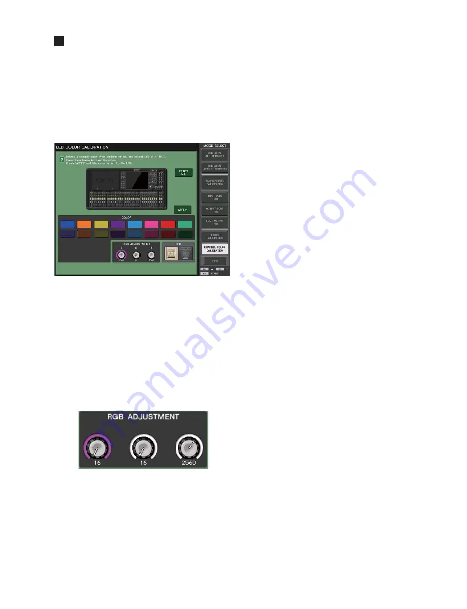
Among MODE SELECT buttons, touch [LED COLOR
CALIBRATION] and the LED COLOR CALIBRATION
window appears. From hear, adjust the color bar and CH
NAME LCD backlight according to the following procedure.
[Manual Operation]
1) Select the color to be adjusted from CH COLORs and
touch it, and the color of the color bar of the main unit
changes accordingly.
2) If there is a channel where color variation is found, press
the
[SEL]
key to select the channel to be changed.
3) Use the CentralLogic RGB ADJUSTMENT and TOUCH
AND TURN encoder to adjust the RGB ADJUSTMENT
values one channel at a time. Colors are in the order of red,
green and blue from the left.
Red
Green
Blue
4) Color adjustment should be done over all the colors until
extreme differences in the color and brightness are not
found.
5) As the final step, press the
[APPLY]
key to store the
adjusted values.
When simultaneously holding down the
32 [SEL]
key and
the
B [SEL]
key
(for QL5)
, or the
16 [SEL]
key and the
B [SEL]
key
(for QL1)
when performing this operation,
the LED calibration value will be also written into the
factory
fi
eld called up by RESET ALL.
6) After adjusting the color bar, adjust the CH NAME LCD
back light and contrast as described hereunder.
[Setting FACTORY Values Manually By Changing
Circuit Boards, etc.]
1) Simultaneously hold down the
32 [SEL]
key and the
B
[SEL]
key
(for QL5)
, or the
16 [SEL]
key and the
B
[SEL]
key
(for QL1)
to turn the power on.
2) The MENU screen will appear, switch to the LED
CALIBRATION screen.
3) If there is a problem with the colors of MULTI COLOR,
press RESET ALL.
(Since the FLASH data may be corrupted, all colors will
be set to their
fi
xed values.)
4) If there are fragmented colors or the
fi
xed values are not
set, press the
B [SEL]
key and adjust the LED, and set
all RGB values to 0, then click
[APPLY]
. Since this will
render the FLASH data corrupt, do this again for item 3 to
set the
fi
xed values.
Then manually perform the settings for each LED with
[Manual Operation]
.
Summary of Contents for QL1
Page 5: ...5 QL5 QL1 QL5 QL1 19 828 4 272 563 Unit 単位 mm 468 272 562 19 DIMENSIONS 寸法図 ...
Page 87: ...87 QL5 QL1 2NA WY63530 Scale 95 100 FX Circuit Board not installed Pattern side パターン側 ...
Page 90: ...QL5 QL1 90 B B DSP32 Circuit Board QL5 DSP16 Circuit Board QL1 2NA ZF60440 ...
Page 91: ...91 QL5 QL1 B B Scale 85 100 Pattern side パターン側 2NA ZF60440 ...
Page 92: ...QL5 QL1 92 HAAD Circuit Board C C 2NA ZH87070 1 ...
Page 94: ...QL5 QL1 94 HAAD Circuit Board D D 2NA ZH87070 1 ...
Page 95: ...95 QL5 QL1 D D Scale 58 100 Pattern side パターン側 2NA ZH87070 1 ...
Page 104: ...QL5 QL1 104 2NA ZF60450 1 PN16M Circuit Board PN16S Circuit Board QL5 F F ...
Page 105: ...105 QL5 QL1 Component side 部品側 2NA ZF60450 1 Scale 90 100 F F ...
Page 108: ...QL5 QL1 108 PNR PNCOM Circuit Board 2NA ZF60470 1 Component side 部品側 ...
Page 109: ...109 QL5 QL1 PNR PNCOM Circuit Board 2NA ZF60470 1 WR 31 0 1 WR 31 0 1 Pattern side パターン側 ...
Page 110: ...QL5 QL1 110 FD1M FDCOM Circuit Board FD2 FDCOM Circuit Board QL5 FD1M FD2 2NA ZK68030 H H ...
Page 111: ...111 QL5 QL1 FD1M FD2 2NA ZK68030 H H Component side 部品側 Scale 90 100 ...
Page 113: ...113 QL5 QL1 Pattern side パターン側 Scale 90 100 not installed I I FD1M FD2 2NA ZK68030 ...
Page 114: ...QL5 QL1 114 Pattern side パターン側 Component side 部品側 FD1S FDCOM Circuit Board WR 6 1 2NA ZK68030 ...


