background image

1

ENGLISH

IMPORTANT SAFETY INSTRUCTIONS

Read before operating equipment

Follow all warnings and instructions marked on this monitor.
1.

Read these instructions.

2.

Keep these instructions.

3.

Heed all warnings.

4.

Follow all instructions.

5.

Do not use this apparatus near water.

6.

Clean only with a dry cloth.

7.

Do not block any ventilation openings. Install in accordance
with the manufacturer's instructions.

8.

Do not install near any heat sources such as radiators, heat
registers, stoves, or other apparatus (including amplifiers)
that produce heat.

9.

Do not defeat the safety purpose of the polarized or
grounding- type plug. A polarized plug has two blades with
one wider than the other. A grounding type plug has two
blades and a third grounding prong. The wide blade or the
third prong are provided for your safety. If the provided plug
does not fit into your outlet, consult an electrician for
replacement of the obsolete outlet.

10. Protect the power cord from being walked on or pinched

particularly at plugs, convenience receptacles, and the
point where they exit from the apparatus.

11. Only use the attachments/accessories specified by the

manufacturer.

12.

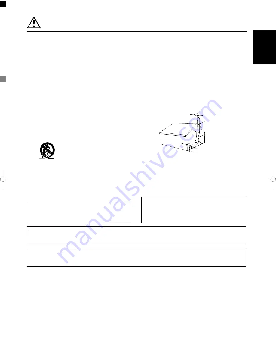
Use only with the cart, stand, tripod, bracket,
or table specified by the manufacturer, or
sold with the apparatus. When a cart is
used, use caution when moving the
cart/apparatus combination to avoid injury
from tip-over.

13. Unplug this apparatus during lightning storms or when

unused for long periods of time.

14. Refer all servicing to qualified service personnel. Servicing

is required when the apparatus has been damaged in any
way, such as power-supply cord or plug is damaged, liquid
has been spilled or objects have fallen into apparatus, the
apparatus has been exposed to rain or moisture, does not

15. Monitors are designed to comply with the recommended

safety standards for tilt and stability.
Do not apply excessive pulling force to the front, or top, of
the cabinet which could cause the product to overturn
resulting in product damage and/or personal injury.

16. Follow instructions for wall, shelf or ceiling mounting as

recommended by the manufacturer.

17. An outdoor antenna should not be located in the vicinity of

overhead power lines or other electrical circuits.

18. If an outside antenna is connected to the receiver be sure the

antenna system is grounded so as to provide some protection
against voltage surges and built up static charges. Section
810 of the National Electric Code, ANSI/NFPA No. 70-1984,
provides information with respect to proper grounding for the
mast and supporting structure, grounding of the lead-in wire
to an antenna discharge unit, size of grounding connectors,
location of antenna-discharge unit, connection to grounding
electrodes and requirements for the grounding electrode.

Note to the CATV system installer: This reminder is provided

to call the CATV system installer's attention to Article 820-40 of the
NEC that provides guidelines for proper grounding and, in
particular, specifies that the cable ground shall be connected to
the grounding system of the building, as close to the point of cable
entry as practical.

Do not place any objects on the top of the monitor which
may fall or cause a child to climb to retrieve the objects.

Disposal of this product may require specific instructions
pertaining to your resident state. For disposal or
recycling information, please contact your local
authorities or the Electronic Industries Alliance:
www.eiae.org.

PREVENTION OF IMAGE RETENTION

Continuous on-screen displays such as video games, stock market quotations, computer generated graphics, and other fixed

(non-moving) patterns can cause permanent damage to the monitor.  

PUBLIC VIEWING OF COPYRIGHTED MATERIAL

Public viewing of programs broadcast by TV stations and cable companies, as well as programs from other sources, may

require prior authorization from the broadcaster or owner of the video program material.

ANTENNA
LEAD IN
WIRE

GROUND
CLAMP

ELECTRIC
SERVICE
EQUIPMENT

NEC NATIONAL ELECTRICAL CODE

ANTENNA
DISCHARGE UNIT
(NEC SECTION 810-20)

GROUNDING CONDUCTORS
(NEC SECTION 810-21)

GROUNDING CONDUCTORS

POWER SERVICE GROUNDING
ELECTRODE SYSTEM
(NEC ART 250 PART H)

011̲PDM-4210̲U̲E    2003.12.23  23:37    ページ 1    (ブラック 版)

Summary of Contents for PDM-4210

Page 1: ...U USER S MANUAL MANUEL UTILISATEUR PDM 4210 High definition plasma monitor Moniteur plasma haute définition ...

Page 2: ...XPOSE THIS MONITOR TO RAIN OR MOISTURE THE MONITOR SHOULD NOT BE EXPOSED TO DRIPPING OR SPLASHING AND OBJECTS FILLED WITH LIQUIDS SUCH AS VASES SHOULD NOT BE PLACED ON THE MONITOR NOTE There are no user serviceable parts inside the monitor Model and serial numbers are indicated on back side of the monitor CAUTION Adjust only those controls that are covered in the instructions as improper changes o...

Page 3: ...roduct damage and or personal injury 16 Follow instructions for wall shelf or ceiling mounting as recommended by the manufacturer 17 An outdoor antenna should not be located in the vicinity of overhead power lines or other electrical circuits 18 If an outside antenna is connected to the receiver be sure the antenna system is grounded so as to provide some protection against voltage surges and buil...

Page 4: ...al devices Compliance with these requirements provides a reasonable level of assurance that your use of this product in a residential environment will not result in harmful interference with other electronic devices This equipment generates uses radio frequencies and if not installed and used according to the instructions found in the users manual may cause interference harmful to the operation of...

Page 5: ... Note for Dealers After installation be sure to deliver this manual to the customer and explain to the customer how to handle the product Notes about This Manual The information in this manual is subject to change without notice While meticulous care has been taken in the preparation of this manual you are requested to notify your dealer or us should you have any comments views or questions about ...

Page 6: ...nts Pedestal PDS 242 Wall Mounting Unit PWK 242 Video Unit PTB 4210 An expansion unit for viewing video with this device This User s Manual was printed before final product development After printing some product specifications may change due to operational upgrades and other reasons In this case the specifications of the product itself will take precedence over the specifications in this manual T...

Page 7: ...t in damage and shorten the lifespan of your monitor due to overheating Make sure there is ample ventilation Keep a space of 100mm 10cm or more between the sides rear and top of the monitor and other objects such as walls Do not place anything around ventilation openings of the monitor Never block ventilation openings Do not put the plasma display panel side up Do not cover the monitor with a tabl...

Page 8: ...Make sure the plus and minus terminals are correctly aligned when loading the battery If you observe a leakage of the battery wipe out the liquid and then replace the battery If the liquid adheres your body or clothes rinse well with water Obey the local laws on disposing the battery Be careful in moving the monitor Neglect could result in an injury or damage Do not move the monitor during use Bef...

Page 9: ...rom Radio Adjust Radio antennas in order for the monitor not to receive interference The antenna cable of Radio should be kept away from the monitor Use a coaxial cable for antenna You can check if this monitor influences Radio receivers by turning off all other equipment other than the monitor If you find a problem receiving Radio when using the monitor check the instructions mentioned above Prec...

Page 10: ... or hard objects Precautions for the installation Do not use makeshift pedestals and NEVER fix legs with wood screws to ensure complete safety always fit the manufacturers approved pedestal or legs with the fixings provided according to the instructions Use only with the cart pedestal tripod bracket or table specified by the manufacturer or sold with the apparatus When a cart is used use caution w...

Page 11: ... button OK button 15 RECALL button SELECT button 16 Adjustment buttons are located on the bottom The back cover is provided with indications to distinguish the adjustment buttons SUB POWER button 14 Control panel VOLUME UP DOWN buttons ADJUST buttons 15 Main power switch 14 14 The main power switch is located at the back on the lower surface Indicating lamp External device connection terminals Rea...

Page 12: ...bout 3m With in 30 degrees About 3m AV1 AV2 RGB 1 RGB 2 AV3 MUTE VOL VOL AV4 AUTO PinP OK SIZE RECALL MENU ID ID SET CAUTION Do not use new and old batteries together The batteries could explode or leak resulting in fires physical injury or stains When loading batteries observe their correct polarities as marked on the product If loaded in the wrong direction the batteries could explode or leak re...

Page 13: ...equate design can cause overturning or dropping and result in fire electrical shock or injury Please note that our company assumes absolutely no responsibility for personal injuries or property damage caused by use of other mount units or improper installation Installation of the wall mount unit and ceiling mount unit can be dangerous so do not attempt this work yourself Ask your dealer to provide...

Page 14: ...ned off 3 Connect the signal input terminal RGB 1 or RGB 2 on the rear panel of this device to the display signal output terminal of the personal computer Use a cable that fits the input terminal of this device and the output terminal of the personal computer Depending on the type of personal computer being connected the use of an optional conversion adapter or the adapter provided with the person...

Page 15: ...erent from this drawing for some countries Connect the power cord after completing all other connections INSTALLATION INSTRUCTIONS continued Power Cord Connection CAUTION Use only the power cord provided Do not use a power supply voltage other than that indicated AC100 240V 50 60Hz as this may cause fire or electric shock ...

Page 16: ...e control or the SUB POWER button on the underside of the front of the frame is ON Lights orange Off Power Save When the main power switch is ON and the ON button on the remote control or the SUB POWER button on the underside of the front of the frame is ON However the indicator also light orange when the unit is in POWER SAVE mode When the indicating lamp lights orange or the message No Sync Sign...

Page 17: ... Input can be switched by pressing the RGB1 RGB2 buttons of the remote control Input can be switched in the sequence of RGB1 RGB2 by pressing the INPUT SELECT button of the monitor When a button is pressed the volume adjustment status guide will be displayed The volume will increase when the VOL or button is pressed while the guide is being displayed The volume will decrease when the VOL or button...

Page 18: ...requency Input vertical frequency The input signal status can be displayed on the screen by pressing the RECALL button of the remote control or the monitor The display will go out in approximately 6 seconds Off timer On timer RGB OPERATING INSTRUCTIONS continued RECALL button Display area selection diagram RGB input Resolution Full display Circular display Display Full Normal Real Zoom1 Zoom2 Zoom...

Page 19: ...s separate control of up to a maximum of seven monitors Remote control ID No 2 initially ID no 1 can be set by pressing the ID SET button for 2 sec or more while holding down the ID button The number will be incremented 2 6 7 1 2 when this button pressed continuously The ID remote control is operated by pressing the various buttons while holding down the ID button Operation is possible only when t...

Page 20: ... adjusted Brightness Black is subdued for increased overall darkness Black is set off for increased overall brightness Adjust to taste Color Darkens colors Lightens colors Adjust to taste Tint Enhances red and weakens green Enhances green and weakens red This is not available for adjustment when receiving PAL SECAM signal In this case the character will be grayed out Adjust for the most realistic ...

Page 21: ...of a stadium Perfect Volume Off On This will automatically adjust volume so each channel and input has the same average volume level Reset Selects the Reset mode The original factory settings for the items of this Menu page can be restored by pressing the OK button Picture Audio Timer Function Setup Language Select OK Set Audio Audio Mode Movie Treble 10 Bass 10 Balance 0 L R SRS TruBass Middle Ma...

Page 22: ...ed out Default Zoom Optional grayed out Reset Selects the Reset mode The original factory settings for the items of this Menu page can be restored by pressing the OK button Panel Life Normal Extend 1 Extend 2 This function suppresses the contrast of the screen regardless of the Contrast setting in the Picture Menu By this control power consumption can be reduced or degradation of a panel can be mi...

Page 23: ...pressing the OK button This is effective only for RGB2 Input Level 0 7V 1 0V Normally set to 0 7 V If white is found to spread across the screen set to 1 0 V This is effective only for RGB2 Frequency Display Off On Set this to Off if the frequency information of the Input Signal Screen Display is not required WVGA Type Off On This is only available for W VGA signal When it is set to On the display...

Page 24: ...very Audio Mode 1 setting is registered Bass Balance 1 setting is registered SRS TruBass For every Audio Mode 1 setting is registered Matrix Surround Perfect Volume Menu Display Registration condition Function Screen Saver 1 setting is registered Screen Wipe not registered Black Side Panel not registered Panel Life 1 setting is registered Mode Display ID Number Inverse Standby White Gamma Setup Au...

Page 25: ... the input signal specifications 28 30 No Sync Signal Changes in the signal status are displayed on the screen as they arise OTHER FEATURES continued RGB2 RGB H 48 4kHz V 60 1 Hz Min OFF RGB Invalid Scan Freq Power Save Mode When the RGB1 RGB2 input is selected When this unit is connected to a VESA DPMS computer the Power Save Off mode can be set to be activated automatically when the computer is ...

Page 26: ...endency of the phosphor is to degrade more the brighter the characters and figures are displayed When images of figures with different levels of brightness as shown in Fig B are continuously displayed for a long period of time it becomes easier for image marks at locations when the brighter figures are displayed to be noticeable The image retention images in this document are exaggerated for the p...

Page 27: ...int to check Check the way the power cable is connected Press the power switch No sync signal is detected Check the way the signal cable is connected Make sure that the switch of the computer imaging equipment etc is turned on Make sure the computer is not in the power save mode Check to see if the input selection matches the connection terminal An input signal is not received normally Check to se...

Page 28: ...ase note that this is not a malfunction High precision technology is used to manufacture the plasma display panel However in some cases there are minor defects in some parts of the screen Please note that this is not a malfunction The plasma display panel is lighting the phosphors by the discharge of internal radiation Depending on the screen contents in rare cases this may cause vertical stripes ...

Page 29: ...ntal Clock adjustment 6 Press the or ADJUST buttons and search for clear characters over the entire screen 7 Perform adjustment for symptom 2 below when the characters are blurred on the entire screen The display image may be momentarily disturbed during clock adjustment but this is not a failure Symptom 2 Text displayed across the screen appears blurred in its entirety figure 2 A fine pattern fli...

Page 30: ...30 W x 636 H x 91 D mm Net weight excluding pedestal 34 9kg Ambient conditions Temperature Operating 5 C to 35 C Storage 0 C to 40 C Relative humidity Operating 20 to 80 Storage 20 to 90 non condensing Power supply AC100 240V 50 60Hz Power consumption at standby 365W 3W Audio output 12W 12W 6Ω RGB input Input signals Input terminals RGB1 DVI input terminal DVI D RGB1 audio input terminal 3 5mm Ste...

Page 31: ...Data3 Frame GND 13 T M D S Data3 With Digital RGB signal input RGB1 input Recommended Signal List Make sure that the signal of the equipment to be connected is compatible with the specifications on this list 1 2 3 4 5 6 7 8 9 10 11 12 13 14 VGA W VGA VESA 640 X 400 70 08 31 47 25 18 Signal Name Resolution Vertical frequency Hz Signal mode No Horizontal frequency kHz Dot clock frequency MHz Remarks...

Page 32: ...arks Signal Name Resolution Vertical frequency Hz 1 VGA 640 X 400 70 08 31 47 25 18 2 640 X 480 59 94 31 47 25 18 3 W VGA 864 X 480 59 94 31 47 34 24 WVGA type On 4 VESA 640 X 480 72 81 37 86 31 50 5 640 X 480 75 00 37 50 31 50 6 640 X 480 85 01 43 27 36 00 7 800 X 600 56 25 35 16 36 00 8 800 X 600 60 32 37 88 40 00 9 800 X 600 72 19 48 08 50 00 10 800 X 600 75 00 46 88 49 50 11 800 X 600 85 06 53...

Page 33: ...31 ENGLISH SUPPLEMENT ...
Page 34: ...r AV4 input that is displayed on the screen at the time If the adaptor included is applied to AV4 input as shown in the drawing it is impossible to receive RGB signal DVI STB and RGB component setup To component video equipment Please use connection cable suitable for the terminal form of video equipment 32 43 Applicable video signals for each input terminal See PRODUCT SPECIFICATIONS for details ...

Page 35: ... 1080i 60 or 720p 60 4 3 Panoramic Zoom Full Cinema Display size selection diagram When you want to Set the display size Input signal Display screen Remarks Play a 4 3 image in a 16 9 screen 4 3 Blanking occurs on both sides Play a 4 3 image in a 16 9 screen with the height and width of the middle of the screen enlarged on equal scales and with both sides appearing somewhat enlarged Panoramic Play...

Page 36: ...4 3 image is displayed over the entire screen in the Panoramic mode parts of the periphery of the image may disappear and or appear distorted in some cases Use the 4 3 mode to view images which were created in 4 3 mode This mode allows 4 3 content to be viewed without picture distortion Press Vertical picture position can be adjusted for Panoramic Zoom and Cinema mode as follows 1 Press the SIZE b...

Page 37: ...uttons the audio of the video will be output from the side on which the speaker icon is located The same video input mode cannot be selected for both screens at the same time Pressing the PinP button or the RETURN button will cancel the 2 pictures display When the Video input is set to RGB Video this Split mode is not possible Refer to the table for 2 pictures Split mode PinP button RETURN button ...

Page 38: ...coding Select Set Return OK Picture Day Color Temp Adjust Color Management Color Decoding Select Set Return OK Picture Color Management On Magenta 60 Red 30 Yellow 0 Green 60 Cyan 30 Blue 0 Reset Reset Select On Off Return OK OK Picture Color Decoding RGB R G B Red 0 Green 60 Color 0 Tint 31 Reset Reset Select Return Exit OPERATING INSTRUCTIONS continued PICTURE MENU Picture Mode Day Next Prev Sel...

Page 39: ...this Menu page can be restored by pressing the OK button YNR Off Low High Performs picture signal noise reduction Turn up to reduce noise CNR Performs color signal noise ßreduction Turn up to reduce noise It will be fixed as Off only when selecting DVI STB mode Film Mode Off On On Automatically detects the movie film material and faithfully reproduces the original film image Off Set to OFF when sw...

Page 40: ...Press the OK button every time the setting is changed Red Darkens red only Lightens red only This adjusts R G B levels or tints to make the color appear natural These settings are independently stored in each of the 4 Color Temperature modes Green Darkens green only Lightens green only Color Darkens colors Lightens colors Tint Enhances red and weakens green Enhances green and weakens red FUNCTION ...

Page 41: ...al Normally set this to Auto The system of the input signal will be automatically recognized If the input signal contains a lot of noise or has a low level at Auto and the operation is erratic set this to match the input signal When the component signal is received this setting is not available grayed out AV2 Same to AV1 AV3 AV4 Video Input AV1 Auto HDTV SDTV DVD This should correspond to the sign...

Page 42: ... match the input signal Approximately 1 sec after adjustment is completed the adjustments will be recorded as shown in the table below OTHER FEATURES Automatic Store Menu Display Registration condition Picture Picture Mode 1 setting is registered Contrast For every input function and every Picture Mode 1 setting is registered Brightness Color Sharpness Tint Color Temperature Contrast Mode YNR CNR ...

Page 43: ...on at standby 365W 3W Audio output 12W 12W 6Ω RGB input Input signals Input terminals RGB1 DVI input terminal DVI D RGB1 audio input terminal 3 5mm Stereo Mini Jack RGB2 analog RGB input terminal D sub 15 pin RGB2 audio input terminal 3 5mm Stereo Mini Jack Video signals 0 7 V 1 0 Vp p analog RGB Recommended Signal 480i 576i 480p 576p 1080i 50 1080i 60 720p 60 Sync signals H V separate TTL level 2...

Page 44: ...D CHASSIS 11 RGB G IN RGB terminal D sub 15 pin connector 1 2 3 4 5 6 7 8 9 10 11 12 13 14 15 When different kinds of input signals are simultaneously input to the monitor via a graphics board or the like the monitor will automatically select the signals in the following priority order There may be instances when correct display is not possible even when displaying the signals listed on the follow...

Page 45: ...ifferentiates the signal modes according to the horizontal and vertical frequencies and the horizontal and vertical sync signal polarities Note that different signals having all these elements alike may be handled as the same signal Displaying images with more than 512 lines of vertical resolution at Full diplay compressed display can result in the interpolation of stripes 1 2 3 4 5 6 7 8 9 10 11 ...

Page 46: ... F R OF GERMANY YAMAHA ELECTRONIQUE FRANCE S A RUE AMBROISE CROIZAT BP70 CROISSY BEAUBOURG 77312 MARNE LA VALLEE CEDEX02 FRANCE YAMAHA ELECTRONICS UK LTD YAMAHA HOUSE 200 RICKMANSWORTH ROAD WATFORD HERTS WD18 7GQ ENGLAND YAMAHA SCANDINAVIA A B J A WETTERGRENS GATA 1 BOX 30053 400 43 VÄSTRA FRÖLUNDA SWEDEN YAMAHA MUSIC AUSTRALIA PTY LTD 17 33 MARKET ST SOUTH MELBOURNE 3205 VIC AUSTRALIA Printed in ...

Page 47: ...tor rear panel Video pin cable S video cable Component video cable Video pin cable Video pin cable Audio pin cable Audio pin cable S video cable S video cable Component video cable Component video cable Video pin cable Audio pin cable S video cable Component video cable Surround back right speaker Presence right speaker Surround right speaker Front right speaker Center speaker Subwoofer Front left...

Page 48: ...age Beispiele für Bildspeichereffekte Exempel på kvarstående bilder Ejemplos de Retención de Imagen Rétention d image La rétention peut être un problème pour les écrans Plasma néanmoins si vous suivez les simples instructions suivantes vous pourrez profiter de votre écrans pendant de longues années YAMAHA a pourvu ses écrans moniteurs plasma de fonctions permettant de réduire la rétention d image ...

Page 49: ...ideo Unit Function in this text can be used as is L appareil vidéo PTB 4210 est fourni en standard avec ce modèle les explications des opérations relatives à la function de la vidéo dans ce texte peuvent donc être utilisées telles quelles PDM 4210 QT43971 NOTE REMARQUES Video Note 2003 12 12 19 29 ページ 1 ブラック 版 ...

Page 50: ...ual thoroughly After reading please store this manual in a safe place for future reference This pedestal is for use only with the following models PDM 4210 PDM 4210E Request an installation specialist to install this unit YAMAHA assumes absolutely no responsibility for injuries and damages that may occur due to improper installation and handling ...

Page 51: ...he Plasma Monitor to the pedestal Product Specifications Parts Configuration Chart Included in the parts package M5 x 20 screws x 4 M6 x 30 screws x 4 Cable clamp x 2 Pedestal base x 1 Support x 2 External Dimensions 700 W x 184 H x 300 D mm 27 9 16 W x 7 1 4 H x 35 7 16 D inches Weight 4 2kg 9 lbs 4 oz Main material Surface treatment Pedestal base Support Aluminum alloy Baked paint finish 1 Inser...

Page 52: ...n holes Ensure that there is sufficient clearance for ventilation The internal temperature of the plasma monitor could elevate possibly resulting in fire Do not alter any parts or use broken parts This could result in the plasma monitor falling causing injury Do not mount the plasma monitor in an unstable location The monitor could fall or break resulting in physical injury CAUTION WARNING YAMAHA ...

Reviews: