background image

Summary of Contents for Outboards 703

Page 1: ...Marine Outboards 703 REMOTE CONTROL BOX OPERATION MANUAL MODE D EMPLOI DE BOITIER DE COMMANDE A DISTANCE T YAMAHA MOTOR CO LTD 703 28199 33 http motorka org ...

Page 2: ...TLE OPENING ADJUSTMENT AT REVERSE 15 POSITIONNEMENT DU BOITIER DE COMMANDE A DISTANCE ET LONGUEUR DES CABLES 6 POSE REMOTE CONTROL BOX FOR TWIN ENGINE 15 CHANGEMENT DE LA POSITION DU LEVIER DE COMMANDE 10 CHANGEMENT D ACCELERATEUR DU TYPE POUSSER POUR OUVRIR AU TYPE TIRER POUR OUVRIR 12 REGLAGE DE L OUVERTURE DE L ACCELERATEUR EN MARCHE ARRIERE 15 NOTES ON STORAGE 16 WIRING 16 BOITIER DE COMMANDE ...

Page 3: ...ntes Ce symbole signale un danger et signifie K ATTENTION DANGER SOYEZ ATTENTIF VOTRE SECURITE EST EN JEU AAVERTISSEMENT Le respect des consignes AVERTISSEMENT est imperatif faute de quoi le conducteur toute personne se trouvant a proximite ou le personnel charge de Pentretien commande a distance risquerait d etre grievement voire mortellement blesse ATTjEMTI ATTENTION indique les consignes qui do...

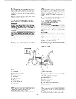
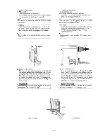
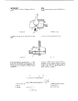
Page 4: ...X X e a t i o n Full open Ouverture maxim ale Ouverture maximale 2 Free Accelerator Place the control lever in the neutral N and turn the neutral throttle lever upward the throttle can be opened without shifting into any gear Use the neutral throttle lever when starting or warming up the engine r CAUTION Only when the control lever in the neutral position the neutral throttle lever can be operated...

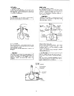
Page 5: ...droite N B Certains modeles ne sont pas equipes du systeme de starter a distance OFF ON START ewttfiewcY F TO P S W R U N O N RD4 I 2 Emergency stop switch The emergency stop switch is provided for the safety of the operator When the lock plate is pulled out from the emergency stop switch the engine stops immediately The engine will not start when the lock plate is remov ed Should the operator fal...

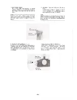
Page 6: ...r le bouton de cet interrupteur le moteur d inclinaison de relevage tourne et regie l angle de fixation du moteur hors bord Quand on relache le bouton le moteur s arrete 4 Adjusting the Stiffness of the Control Lever By turning in or out the throttle friction screw at the front of the remote control box the stiffness of the control lever can be adjusted Turning the screw to the right makes the con...

Page 7: ...ire tourner le moteur au ralenti et lui permettre ainsi de refroidir Ensuite rentrer directement au port le plus proche a faible vitesse NOTE NoB Type without overheat warning buzzer is available Le modele sans signal sonore de surchauffe est disponible 6 Neutral Switch The neutral switch keeps the engine from starting with gears are shifted in When the control lever is in Forward or Reverse the e...

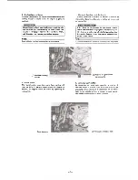
Page 8: ...length should be equal to the sum Position the remote control cables and check if they are long enough Connect the cables to the engine and make sure they do not get tangled or bent when the steering wheel is turned CAUTION Avoid bending the cables sharply that is make sure the cables do not from a loop with a diameter of less than 406mm 16in 1 Position du Boitier de Commande a Distance Le boitier...

Page 9: ... the remote control cables and tighten the lock nuts Before installing the cable joints apply the water resistance grease Yamaha Grease A to the holes in the cable joints 3 Visser les raccords de cable accessoires d environ 11 mm 0 4 po sur les extremites des cables de commande a distance puis serrer les contre ecrous Avant de monter les raccords de cable mettre de la graisse etanche Graisse Yamah...

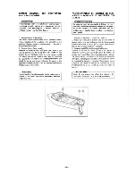
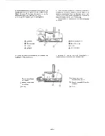
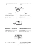
Page 10: ...accord de cable sur la goupille de rextremite du bras d inversion puis le bloquer avec le circlip 5 Ajuster Poeillet en caoutchouc accessoire dans la gorge dela bride T Grommet 2 Clamp groove 3 Circlip 4 Shift arm T Oeillet en caoutchouc 2 Gorge de la bride 3 Circlip 4 Bras d inversion 6 Connect the remote control cable for the throttle to the throttle arm in the same manner 6 Raccorder le cable d...

Page 11: ...r is turned further from this position to Forward the throttle fully opens Next make sure that when the control lever is returned to N the throttle is completely closed If not fully closed adjust the positions of cable joints on the engine side and install them again 9 Conformement aux instructions donnees dans le Manuel du proprietaire du moteur hors bord raccorder les cables de commande d invers...

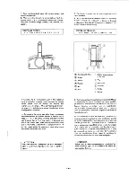
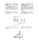
Page 12: ...ote gauche ou vice versa 1 Saisir les deux cotes du cache de cables et le tirer pour Tenlever 2 A l aide d une cle a douille de 12 mm desserrer le boulon 3 Place a punch on the bolt head and by tapping it with a hammer remove the control lever from the remote control box r CAUTION Use care not to damage power trim and tilt switch leads 3 Mettre un pointeau sur la tete du boulon et en tapant dessus...

Page 13: ...RRAGE 3 4 Nm 0 3 0 4 m kg 2 2 2 9 ft lb V en JlilL 0 w V en 0 e Lh I f 6 Install the control lever and secure it by screwing in the bolt from the back side and with the washer 6 Monter le levier de commande et le fixer en vissant le boulon muni de sa rondelle par derriere TIGHTENING TORQUE 1 0 1 1 Nm 1 0 1 1 m kg 7 2 7 9ft lb COUPLE DE SERRAGE 1 0 11 N m l 0 1 1m kg 7 2 7 9 ft lb 7 While taking ca...

Page 14: ...mmande a distance permet de changer l accelerateur du type poursser pour ouvrir au type tirer pour ouvrir en changeant certaines des pieces et leurs positions Ce manuel decrit la procedure de changement du type pousser pour ouvrir au type tirer pour ouvrir Par consequent si on veut changer l accelerateur du type tirer pour ouvrir au type pousser pour ouvrir il suffit d inverser cette procedure H M...

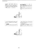
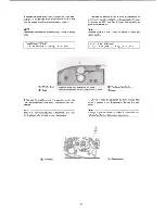
Page 15: ... Nm 0 15 0 18 m kg 1 1 1 3 ft lb COUPLE DE SERRAGE 1 5 1 8 Nm 0 15 0 18 m kg 1 1 1 3 ft lb Throttle drum 2 Roller Turn the drum 180 and install the lever Tourner le tambour de 180 puis mooter le levier T Tambour deceleration 2 Galet 4 Remove the throttle arm for the push to open throttle type and install the throttle arm for the pull to open throt tle type 4 Enlever le bras d acceleration du type ...

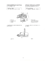
Page 16: ... fente Ensuite fixer le dos superieur avec ses trois vis TIGHTENING TORQUE 1 5 1 8 Nm 0 15 0 18 m kg 1 1 1 3 ft lb COUPLE DE SERRAGE 1 5 1 8 Nm 0 15 0 18m kg 1 1 1 3 ft lb T Main shaft 2 Throttle arm shaft 3 Drive pin T Axe principal 2 Axe de bras d acceleration 3 Goupille d entrainement 6 Secure the lower back panel with the two screws and install the wire cover 6 Fixer le dos inferieur avec ses ...

Page 17: ... perte de con trole Regler le levier de commande de maniere telle qu9 il ne toairae das de plus de 60 vers la position R marche arriere T Lock nut 2 Adjusting bolt T Contre ecrou 2 Boulon de reglage 3 After adjusting tighten the adjusting bolt lock nut 3 Apres le reglage resserrer le contre ecrou du boulon de reglage TIGHTENING TORQUE 1 5 1 8 Nm 0 15 0 18 m kg 1 1 1 3 ft lb COUPLE DE SERRAGE 1 5 1...

Page 18: ...r de commande a distance surtout sur les faces de contact des pieces mobiles S il y a de la rouille l eliminer puis graisser 3 Eviter autant que possible de courber les cables S ils doivent etre enroules le diametre d un tour doit etre superieur a un metre 40 po 4 Choisir un endroit sec pour le remisage WIRING NOTE Depending on the specification some models are not equipped with the power trim and...

Page 19: ...teur de dispositif d inclinaison et de relevage et vibreur de signalisa tion de surchauffe OFF O Q H t o o o o o W B OFF ON Oo T Power trim and tilt switch 2 Main switch 3 Overheat warning buzzer 4 Neutral switch 5 Lead wire cover 6 Engine stop switch D Interrupteur de dispositif d inclinaison et de relevage 2 Contacteur principal 3 Vibreur de signalisation de surchauffe Contacteur de point mort 5...

Page 20: ...YAMAHA YAMAHA MOTOR CO LTD 2500 SHINGAI IWATA SHIZUOKA JAPAN Printed in Japan MAR 1995 7 Ox 1 Q ...

Reviews: