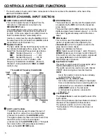
CONTROLS AND THEIR FUNCTIONS
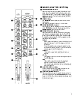
The head number of each control name corresponds to the same number of the illustration at the back of the
attached PLANNING SHEET.
MIXER (CHANNEL INPUT SECTION)
GAIN Control and CLIP Indicator
This control adjusts the level of signals from the
microphone or instruments connected to the
MIC/LINE INPUT jacks.
If the CLIP indicator above each of the knobs (1-4)
remains illuminated, it means that the input level is
too high. In this case, adjust to an optimum level so
that the indicator flickers momentarily at the
maximum volume level by using the GAIN control or
the output level of the connected unit. (GAIN controls
are provided only for channels 1-4).
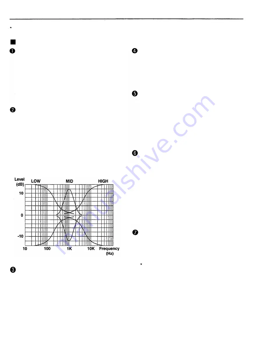
Equalizer Controls
The high, middle and low band frequency levels can
be controlled individually within a range of ±12 dB
based from the standard frequencies given below.
HIGH: Standard frequency .........10 kHz
MID: Standard frequency ......... 1 kHz
LOW: Standard frequency .........100 Hz
When the control is at the "0" position, a flat
frequency characteristic is obtained. (However,
channels 5-8 are provided with HIGH and LOW
controls only.)
The equalizer's frequency characteristics
ASSIGN Switches
These switches are used to send the signals which
are adjusted by the PAN control to the respective
group buses.
These switches and the PAN control can be used to
distribute signals freely between groups 1-4. On the
other hand, signals are always sent to the stereo
buses.
PAN Control
This control is used for adjusting balance and
position of signals which was adjusted by the
channel fader, when the signals are sent to the
group buses or stereo buses.
Signals are distributed as follows:
ODD/L: Signals are sent to Groups 1 and/or 3 Stereo L).
EVEN/R: Signals are sent to Groups 2 and/or 4 Stereo R).
If the control is set to the center position, signals will
be equally distributed to both the ODD/L and
EVEN/R groups or channels.
Input Selector Switch
This switch is used to select the input signal (either
TAPE or MIC/LINE) for each channel.
This switch can also be used to turn each channel
ON/OFF when mixing down recorded sources.
TAPE:
Set to this position in order to input an already-
recorded signal to the mixer.
MIC/LINE (ch 1-4), LINE (ch 5-8):
Set to this position when adding an input signal
from an instrument such as an electric guitar or a
keyboard which is connected to the MIC/LINE
(LINE) INPUT jacks on the rear panel.
A microphone may also be connected for
channels 1-4.
Channel Fader
The channel fader is used to adjust the level of the
input signals.
When mixing channels, input level balance between
channels can be adjusted with these faders.
The optimum position is at 7-8 on the scale.
AUX 1 and 2 Controls
The AUX controls are used to adjust the level of
signals input to a unit such as an external signal
processor connected to the AUX SEND jack(s).
The signals adjusted by these controls are sent from
the AUX bus line to the connected signal
processor(s) via the AUX SEND jack(s). The signals
then return to this unit's group buses and stereo
buses via the AUX RETURN jacks.
Set the fader to "0" for channels which are not
being used.
8
Summary of Contents for MT8X
Page 1: ...YAMAHA AUTHORIZED PRODUCT MANUAL MULTITRACKCASSETTERECORDER ...
Page 2: ...YAMAHA MULTITRACK CASSETTE RECORDER OPERATION MANUAL ...
Page 41: ...CONNECTION EXAMPLE 40 ...
Page 46: ......
Page 47: ...TRACK SHEET TITLE ARTIST ENGINEER DATE COMPOSER ARRANGER ...
Page 48: ...YAMAHA R0 1 93 08 2500 YAMAHA CORPORATION RO Box1 Hamamatsu Japan VQ02780 ...


