background image

2

Controles del panel frontal

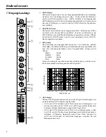
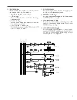
Canal de entrada

1

Control de Ganancia (GAIN)
Este control sirve para ajustar la sensibilidad de entrada de cada canal de
entrada, desde -16dB hasta -60dB para cada fuente de micrófono mediante los
conectores de entrada XLR, y desde +10dB hasta -26dB para cada fuente de
línea mediante los conectores de entrada de la toma de auriculares. Para
conseguir un rendimiento óptimo, ajuste el control de Ganancia (GAIN) para
que el diodo fotoemisor indicador de Máximo (PEAK) se ilumine de vez en
cuando.

2

Interruptor Línea/Micrófono (LINE/MIC)
Este interruptor permite cambiar la entrada de micrófono (MIC IN). Empuje
este interruptor hacia adentro (hacia Micrófono (MIC)) cuando haya un
micrófono conectado al conector de entrada de micrófono (MIC IN). Coloque
el interruptor en Línea (LINE) cuando haya una fuente de línea conectada al
conector de entrada de línea (LINE IN).

3

EQ
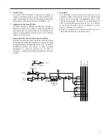
La sección equalizador que hay en cada canal de entrada consiste en controles
de nivel Bajo (LOW), Bajo Medio (LO-MID), Alto Medio (HI-MID) y Alto
(HIGH) que pertenecen a las siguientes frecuencias con una amplitud máxima
de +15dB.

Alto (HIGH)

: 12kHz

Alto Medio (HI-MID)

: 3kHz

Bajo Medio (LO-MID)

: 300kHz

Bajo (LOW)

: 80Hz

La respuesta en frecuencia será plana cuando cada control esté fijado en el
centro.

50


100

    200


500


1k


2k


  5k


10k


20k

FREQUENCY (Hz)

+20

+15

+10

+5

0

–5

–10

–15

–20

RESPONSE (dB)

4

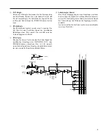
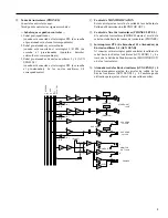
Controles de Envío Auxiliar (AUX send)
Cada control auxiliar (AUX) determina el nivel de la señal enviada desde los
canales de entrada hacia el bus de mezclas auxiliar numerado de forma
correspondiente a los canales de entrada.
• El AUX1 y el AUX2 vienen preconectados de fábrica para su

funcionamiento post-atenuador, de forma que las señales AUX1 y AUX2
se ven afectadas por el ajuste del atenuador de canal.

• El AUX3 y el AUX4 vienen preconectados de fábrica para su

funcionamiento pre-atenuador, de forma que las señales AUX3 y AUX4 no
se ven afectadas por el ajuste del atenuador de canal. Por lo tanto, la señal
puede salir o bien hacia el AUX3 o hacia el AUX4 como salida auxiliar, en
lugar de utilizar las salidas estereofónicas.

GAIN

+10   –16  –60 –26

LINE
MIC

HI-
MID

–12      +12

HIGH

–15      +15

LO-
MID

–12      +12

LOW

–15      +15

AUX
1

0        10

AUX
2

0        10

AUX
3

0        10

AUX
4

0        10

PAN

L        R

P

O

S
T

P
R
E

PEAK

PFL

10

5
0

5

10

15
20

30

40

00

1

2

3

4

5
6
7

8

Summary of Contents for MM1242

Page 1: ...5 15 AUX 1 0 10 AUX 2 0 10 AUX 3 0 10 AUX 4 0 10 PAN L R P O S T P R E PEAK PFL 10 5 0 5 10 15 20 30 40 00 GAIN 10 16 60 26 LINE MIC HI MID 12 12 HIGH 15 15 LO MID 12 12 LOW 15 15 AUX 1 0 10 AUX 2 0 1...

Page 2: ...ations If this product is found to be the source of interference which can be determined by turning the unit OFF and ON please try to eliminate the problem by using one of the following measures Reloc...

Page 3: ...reo mix output PFL Pre Fader Listen function allows you to monitor any channel input and ST L R AUX 3 4 output through monitor output or headphones All input channels are available for both microphone...

Page 4: ...EE YAMAHA CORPORATION 1 Location Keep the unit away from locations where it is likely to be exposed to high temperatures or humidity such as near radiators stoves etc Also avoid locations which are su...

Page 5: ...5dB HIGH 12kHz HI MID 3kHz LO MID 300Hz LOW 80Hz Frequency response will be flat when each control is set to the center 50 100 200 500 1k 2k 5k 10k 20k FREQUENCY Hz 20 15 10 5 0 5 10 15 20 RESPONSE dB...

Page 6: ...ector This is useful when you wish to monitor only the signal from a particular channel or take a countermeasure for a problem 8 Fader This is the main level control for each input channel It de termi...

Page 7: ...nd 2 5 OUTPUT LEVEL AUX 3 4 meters These meters show the level of output signal appearing at the AUX SEND 3 and 4 6 OUTPUT LEVEL L R meters These meters show the level of output signal appearing at th...

Page 8: ...EL control The PHONES control adjusts the level of the signal sent to the PHONES jack C AUX SEND 3 4 PFL switches Turning this switch ON will allow you to monitor the signal output to AUX SEND 3 and 4...

Page 9: ...can use these as auxiliary inputs 5 STEREO OUT These are XLR type connectors used to connect a power amplifier Pin assignment 1 GND 2 hot 3 cold 6 MONITOR OUT These are unbalanced phone jacks used to...

Page 10: ...ge monitors Front of house main speakers Power amp STEREO OUT Power amp MONITOR OUT Graphic EQ Headphone 88 Mic and line inputs 1 12 MIXER PHANTOM POWER OUTPUT LEVEL 88 AUX RTN2 AUX RTN1 AUX SEND2 AUX...

Page 11: ...nnel AUX control nominal Maximum voltage gain 84dB MIC IN ST OUT 50dB LINE IN ST OUT 86dB MIC IN AUX SEND1 2 80dB MIC IN AUX SEND3 4 90dB MIC IN MONITOR OUT 30dB AUX RETURN ST OUT Crosstalk 70dB adjac...

Page 12: ...jack 1 4 38 8mV 245mV 0dB 0 775Vrms Output Specifications Output Nominal Output level Output Connector type impedance impedance Nominal level ST OUT L R 150 600 Lines 4dB 1 23V 24dB 12 3V XLR 3 32 typ...

Page 13: ...ITOR OUT 4dB R L PFL METER 3 4 4dB 1 2 4dB AUX SEND METER MONITOR MONITOR METER PFL PFL PFL CTRL PHANTOM OFF ON PHANTOM 48V AUX PFL 4 3 2 1 R L STEREO R L STEREO OUT 4dB PHONES AUX SEND 1 4 10dB ST AU...

Page 14: ...MELANGEUR MANUEL D INSTRUCTIONS Fran ais...

Page 15: ...en coute avant curseur elle vous permet de contr ler n im porte quel canal d entr e ainsi que les sorties ST L R AUX 3 4 via moniteur ou casque Tous les canaux d entr e acceptent une entr e micro ou u...

Page 16: ...aration un technicien Yamaha qualifi Toute tentative d ouver ture du bo tier et de manipulation des circuits internes se soldera par la perte du b n fice de la garantie 5 Coupez toujours l alimentatio...

Page 17: ...nces suivantes avec une plage maximale de 15dB HIGH 12kHz HI MID 3kHz LO MID 300Hz LOW 80Hz La r ponse en fr quence sera plate si vous r glez chaque commande au cen tre 50 100 200 500 1k 2k 5k 10k 20k...

Page 18: ...u PHONES Cela vous permet de contr ler le signal d un canal donn ou de prendre une mesure pour r soudre un probl me particulier 8 Curseur C est la commande de niveau principale pour chaque ca nal d en...

Page 19: ...rtie du bus AUX SEND 1 et 2 5 Indicateurs OUTPUT LEVEL AUX 3 4 Ces indicateurs donnent le niveau du signal sortant par les bus AUX SEND 3 et 4 6 Indicateurs OUTPUT LEVEL L R Ces indicateurs donnent le...

Page 20: ...mmande PHONES LEVEL Cette commande d termine le volume du signal envoy au casque par la borne PHONES C Commutateur PFL AUX SEND 3 4 Lorsque vous enfoncez ce commutateur le signal des bus AUX SEND 3 et...

Page 21: ...plificateur du retour de sc ne Vous pouvez y couter les signaux suivants Signaux pouvant tre contr l s 1 Signal apr s EQ lorsque le commutateur PFL du canal correspondant est enfonc 2 Signal ST avant...

Page 22: ...e sc ne Haut parleurs de salle Amplificateur STEREO OUT Amplificateur MONITOR OUT Eqaliseur graphique Casque 88 Entr es ligne et micro 1 12 MIXER PHANTOM POWER OUTPUT LEVEL 88 AUX RTN2 AUX RTN1 AUX SE...

Page 23: ...e commande de canal AUX Niveau nominal Gain maximum 84dB MIC IN ST OUT 50dB LINE IN ST OUT 86dB MIC IN AUX SEND1 2 80dB MIC IN AUX SEND3 4 90dB MIC IN MONITOR OUT 30dB AUX RTN ST OUT S paration des ca...

Page 24: ...0db 0 775 Vrms Caract ristiques de sortie Imp dance Imp dance Niveau de sortie Sortie Type de connecteur de sortie nominale Niveau nominal ST OUT L R 150 600 Lines 4dB 1 23V 24dB 12 3V XLR 3 32 type...

Page 25: ...T MONITOR OUT 4dB R L PFL METER 3 4 4dB 1 2 4dB AUX SEND METER MONITOR MONITOR METER PFL PFL PFL CTRL PHANTOM OFF ON PHANTOM 48V AUX PFL 4 3 2 1 R L STEREO R L STEREO OUT 4dB PHONES AUX SEND 1 4 10dB...

Page 26: ...timmung mit den Bestimmungen der 82 499 EWG EG Richtlinie funkentst rt ist Der Deutschen Bundespost wurde das Inverkehrbringen dieses Ger tes angezeigt und die Berechtigung zur berpr fung der Serie au...

Page 27: ...it der Sie das Eingangssignal jedes beliebigen Kanals Eingangskan le ST L R sowie AUX 3 und 4 abh ren k nnen Das Signal des betreffen den Kanals wird dann an MONITOR OUT und PHONES angelegt Alle Einga...

Page 28: ...aha Kunden dienst Bitte bedenken Sie da beim ffnen des Geh uses automatisch der Garantieanspruch erlischt 5 Schalten Sie das Pult aus bevor Sie die Anschl sse vornehmen oder ndern Schalten Sie das MM1...

Page 29: ...nkung dieser Frequenzb nder betr gt jeweils 15dB HIGH 12kHz HI MID 3kHz LO MID 300Hz LOW 80Hz Wenn sich ein Regler in der Mitte auf dem Punkt befindet wird das betref fende Frequenzband weder angehobe...

Page 30: ...nden Kanalzuges der MONITOR OUT oder PHONES Summe zuzuordnen Das ist z B sinnvoll wenn Sie das Signal eines Kanals getrennt abh ren m ch ten um eventuelle Korrekturen durchzuf hren 8 Schieberegler Fad...

Page 31: ...AUX SEND Regler Mit diesen Reglern bestimmen Sie den Ausgangspegel der AUX SEND 1 und 2 Summe 5 OUTPUT LEVEL AUX 3 4 Meter Diese Meter zeigen den Pegel des Signals an das an den Buchsen AUX SEND 3 un...

Page 32: ...B PHONES LEVEL Regler Mit dem PHONES Regler k nnen Sie den Ausgangspegel der PHONES Buchse einstellen C AUX SEND 3 4 PFL Taster Wenn Sie diese Taster dr cken wird das Signal der AUX SEND 3 und 4 Summe...

Page 33: ...gelegt die Sie mit den Eing ngen der Endstufe verbinden m s sen Stiftbelegung 1 Masse 2 hei 3 kalt 6 MONITOR OUT Buchsen An diese asymmetrischen Klinkenbuchsen k nnen Sie die Endstufe der B hnenbescha...

Page 34: ...monitore Saalbeschallung Endstufe STEREO OUT Endstufe MONITOR OUT Graphischer Equalizer Kopfh rer 88 Mikrofon und Line Eing nge 1 12 MIXER PHANTOM POWER OUTPUT LEVEL 88 AUX RTN2 AUX RTN1 AUX SEND2 AUX...

Page 35: ...4dB MIC IN ST OUT 50dB LINE IN ST OUT 86dB MIC IN AUX SEND1 2 80dB MIC IN AUX SEND3 4 90dB MIC IN MONITOR OUT 30dB AUX RTN ST OUT Kanaltrennung 70dB bei nebeneinanderliegenden Kan len 60dB Eingang zu...

Page 36: ...linkenbuchse 0dB 0 775Vrms Ausgangsspezifikationen Ausgangs Nenn Ausgangspegel Ausgang Anschlu typ impedanz impedanz Nennpegel ST OUT L R 150 600 Lines 4dB 1 23V 24dB 12 3V XLR 3 32 Typ Symmetrisch AU...

Page 37: ...T MONITOR OUT 4dB R L PFL METER 3 4 4dB 1 2 4dB AUX SEND METER MONITOR MONITOR METER PFL PFL PFL CTRL PHANTOM OFF ON PHANTOM 48V AUX PFL 4 3 2 1 R L STEREO R L STEREO OUT 4dB PHONES AUX SEND 1 4 10dB...

Page 38: ...MEZCLA MANUAL DE OPERACI N Espa ol...

Page 39: ...n PFL Escucha al Pre Atenuador le permite controlar cualquier entrada de canal y salida STL R AUX3 4 a trav s de la salida de monitorizaci n o de los auriculares Todos los canales de entrada se pueden...

Page 40: ...abores de reparaci n o mantenimiento avise a personal cualificado de Yamaha Si abre la cubierta y o intenta forzar los circuitos internos la garant a quedar anulada 5 Apague siempre el aparato antes d...

Page 41: ...rtenecen a las siguientes frecuencias con una amplitud m xima de 15dB Alto HIGH 12kHz Alto Medio HI MID 3kHz Bajo Medio LO MID 300kHz Bajo LOW 80Hz La respuesta en frecuencia ser plana cuando cada con...

Page 42: ...rizaci n MONITOR OUT o de Auriculares PHONES Resulta til cuando se desea controlar nicamente la se al que proviene de un canal en particular o adoptar una medida para intentar solucionar un fallo 8 At...

Page 43: ...Izquierdo y Derecho OUTPUT LEVEL L R Estos medidores muestran el nivel de la se al de salida que aparece en el conector de Salida Estereof nica STEREO OUT 7 Indicador PHANTOM El diodo fotoemisor del...

Page 44: ...MONITOR OUT B Control de Nivel de Auriculares PHONES LEVEL El control de Auriculares PHONES ajusta el nivel de la se al enviada hacia las tomas de Auriculares PHONES C Interruptores PFL de Escucha al...

Page 45: ...6 Salida de Monitorizaci n MONITOR OUT Se trata de tomas de auriculares no sim tricas que se utilizan para conectar los altavoces de monitorizaci n Se pueden monitorizar las siguientes se ales Se ales...

Page 46: ...pales frente al edificio Amplificador de potencia STEREO OUT Amplificador de potencia MONITOR OUT Ecualizador gr fico Auriculares 88 Micr fonos l nea entradas 1 12 MIXER PHANTOM POWER OUTPUT LEVEL 88...

Page 47: ...NE IN ST OUT 86dB MIC IN AUX SEND 1 2 80dB MIC IN AUX SEND 3 4 90dB MIC IN MONITOR OUT 30dB AUX RETURN ST OUT Interferencia entre canales 70dB canales de entrada adyacentes 60dB entrada a salida excep...

Page 48: ...mV 245mV estereof nica 0dB 0 775 Vrms Especificaciones de Salida Impedancia Impedancia Nivel de Salida Salida Tipo de Conector de Salida Nominal Nivel Nominal ST OUT L R 150 600 Lines 4dB 1 23V 24dB 1...

Page 49: ...MONITOR OUT 4dB R L PFL METER 3 4 4dB 1 2 4dB AUX SEND METER MONITOR MONITOR METER PFL PFL PFL CTRL PHANTOM OFF ON PHANTOM 48V AUX PFL 4 3 2 1 R L STEREO R L STEREO OUT 4dB PHONES AUX SEND 1 4 10dB ST...

Page 50: ...YAMAHA CORPORATION R0 1 IP Printed in Korea P O Box 1 Hamamatsu Japan...

Reviews: