


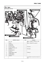
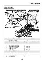
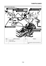


THROTTLE BODY
7-6
EAS2DM1089
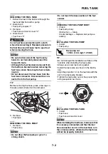
REMOVING THE FUEL HOSE
1. Disconnect:
• Fuel hose
Refer to “REMOVING THE FUEL TANK” on
page 7-2.
EAS26980
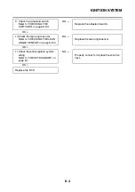
CHECKING THE FUEL INJECTOR
1. Check:
• Injector
Obstruction
→
Replace and check the fuel
pump/fuel supply system.
Deposit
→
Replace.
Damage
→
Replace.
2. Check:
• Injector resistance
Refer to “CHECKING THE FUEL INJEC-
TOR” on page 7-6.
EAS26990
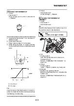
CHECKING THE THROTTLE BODY
1. Check:
• Throttle body
Cracks/damage
→
Replace the throttle body.
2. Check:
• Fuel passages
Obstructions
→
Clean.
▼▼▼
▼
▼ ▼▼▼
▼
▼ ▼▼▼
▼
▼ ▼▼▼
▼
▼ ▼▼▼
▼
▼ ▼▼▼
▼
▼▼▼
a. Wash the throttle body in a petroleum-based
solvent.
Do not use any caustic carburetor cleaning
solution.
b. Blow out all of the passages with compressed
air.
▲▲▲
▲
▲ ▲▲▲
▲
▲ ▲▲▲
▲
▲ ▲▲▲
▲
▲ ▲▲▲
▲
▲ ▲▲▲
▲
▲▲▲
EAS2DM1090
INSTALLING THE INTAKE MANIFOLD
1. Install:
• Intake manifold joint “1”
• Intake manifold “2”
TIP
Make sure that the projection “a” on the intake
manifold joint is facing down.
EAS2DM1091
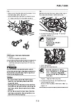
INSTALLING THE FUEL HOSE
1. Install:
• Fuel hose
• Fuel hose connector cover
NOTICE
ECA2DM1039
When installing the fuel hose, make sure that
it is securely connected, and that the fuel
hose connector cover is in the correct posi-
tion, otherwise the fuel hose will not be prop-
erly installed.
TIP
• Wipe up any fuel remaining in the recess “a” in
the fuel pump with a dry rag “1”.
• After installing the fuel hose connector cover
“2”, make sure that it is installed securely.
EAS2DM1092
INSTALLING THE THROTTLE BODY
1. Install:
• Throttle body
TIP
Align the projection “a” on the throttle body with
the slot “b” in the throttle body joint.
a
2
1
a
1
2
Summary of Contents for MBK XMAX 2014
Page 1: ...2014 SERVICE MANUAL YP125R YP125RA 2DM F8197 E0 ...
Page 6: ......
Page 8: ......
Page 64: ...TIGHTENING TORQUES 2 17 Muffler tightening sequence 1 2 3 ...
Page 72: ...LUBRICATION SYSTEM DIAGRAMS 2 25 EAS2DM1116 LUBRICATION SYSTEM DIAGRAMS 1 2 3 4 5 3 ...
Page 78: ...CABLE ROUTING 2 31 Steering head front view 1 2 3 4 5 6 8 8 A 7 7 ...
Page 80: ...CABLE ROUTING 2 33 Front brake left side view for YP125R 1 2 2 1 1 2 2 D E A B C ...
Page 82: ...CABLE ROUTING 2 35 Front brake left side view for YP125RA 2 1 1 2 1 2 2 A B D E C ...
Page 92: ...CABLE ROUTING 2 45 Frame right side view 3 2 4 1 2 3 A B 6 5 3 A B 3 3 2 3 3 A A B A B B 3 ...
Page 94: ...CABLE ROUTING 2 47 Engine right side view 6 6 6 6 C D C D D C 10 B 9 5 6 1 2 8 3 4 5 6 7 A ...
Page 98: ...CABLE ROUTING 2 51 Frame left side view C D C D 2 1 E 1 2 D C 6 1 4 5 3 2 1 7 3 2 1 A B ...
Page 100: ...CABLE ROUTING 2 53 Engine left side view 1 1 1 1 1 2 3 4 5 6 7 8 9 7 7 A B A B A B 1 ...
Page 106: ...CABLE ROUTING 2 59 Rear brake right side view 2 2 2 2 2 2 1 1 2 3 A B C 3 ...
Page 110: ...CABLE ROUTING 2 63 ...
Page 228: ...REAR SHOCK ABSORBER ASSEMBLIES AND SWINGARM 4 89 ...
Page 231: ......
Page 291: ...CRANKSHAFT 5 60 a 1 ...
Page 292: ...CRANKSHAFT 5 61 ...
Page 302: ...WATER PUMP 6 9 ...
Page 313: ......
Page 331: ...CHARGING SYSTEM 8 18 ...
Page 349: ...COOLING SYSTEM 8 36 ...
Page 391: ...FUEL PUMP SYSTEM 8 78 ...
Page 400: ...IMMOBILIZER SYSTEM 8 87 a Light on b Light off ...
Page 401: ...IMMOBILIZER SYSTEM 8 88 ...
Page 405: ...ABS ANTI LOCK BRAKE SYSTEM for YP125RA 8 92 ...
Page 439: ...ABS ANTI LOCK BRAKE SYSTEM for YP125RA 8 126 ...
Page 464: ...ELECTRICAL COMPONENTS 8 151 ...
Page 476: ......
Page 477: ......
Page 478: ......