CRANKSHAFT
5-58
EAS2DM1082
CHECKING THE OIL STRAINERS
1. Check:
• Oil strainers
Damage
→
Replace.
Contaminants
→
Clean with solvent.
EAS2DM1083
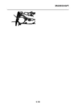
INSTALLING THE CRANKSHAFT
1. Lubricate:
• Oil seals
• Bearings
• Oil pump drive gear
2. Install:
• Oil seal “1”
(to the left crankcase)
3. Install:
• Bearing
(to the right crankcase)
4. Install:
• Crankshaft assembly “1”
TIP
• Install the crankshaft assembly with the crank-
shaft installer pot “2”, crankshaft installer bolt
“3”, adapter “4”, and fork seal driver attachment
“5”.
• The fork seal driver attachment should only
contact the inner race of the bearing.
NOTICE
ECA13970
To avoid scratching the crankshaft and to
ease the installation procedure, lubricate the
oil seal lips with lithium-soap-based grease
and each bearing with engine oil.
TIP
Hold the connecting rod at top dead center
(TDC) with one hand while turning the nut of the
crankshaft installer bolt with the other. Turn the
crankshaft installer bolt until the crankshaft as-
sembly bottoms against the bearing.
5. Install:
• Oil pump drive gear “1”
TIP
Install the oil pump drive gear with the crankshaft
installer pot “2”, crankshaft installer bolt “3”, and
adapter “4”.
Recommended lubricant
Oil seal
Lithium-soap-based grease
Bearing, oil pump drive gear
Engine oil
Oil seal installed depth
0–0.5 mm (0–0.020 in)
a. Oil seal installed depth
1
a
Crankshaft installer pot
90890-01274
Installing pot
YU-90058
Crankshaft installer bolt
90890-01275
Bolt
YU-90060
Adapter (M14)
90890-01478
Adapter #6
YM-90066
Fork seal driver attachment
90890-01186
Replacement 27 mm
YM-A9409-1
3
2
4
5
1
Summary of Contents for MBK XMAX 2014
Page 1: ...2014 SERVICE MANUAL YP125R YP125RA 2DM F8197 E0 ...
Page 6: ......
Page 8: ......
Page 64: ...TIGHTENING TORQUES 2 17 Muffler tightening sequence 1 2 3 ...
Page 72: ...LUBRICATION SYSTEM DIAGRAMS 2 25 EAS2DM1116 LUBRICATION SYSTEM DIAGRAMS 1 2 3 4 5 3 ...
Page 78: ...CABLE ROUTING 2 31 Steering head front view 1 2 3 4 5 6 8 8 A 7 7 ...
Page 80: ...CABLE ROUTING 2 33 Front brake left side view for YP125R 1 2 2 1 1 2 2 D E A B C ...
Page 82: ...CABLE ROUTING 2 35 Front brake left side view for YP125RA 2 1 1 2 1 2 2 A B D E C ...
Page 92: ...CABLE ROUTING 2 45 Frame right side view 3 2 4 1 2 3 A B 6 5 3 A B 3 3 2 3 3 A A B A B B 3 ...
Page 94: ...CABLE ROUTING 2 47 Engine right side view 6 6 6 6 C D C D D C 10 B 9 5 6 1 2 8 3 4 5 6 7 A ...
Page 98: ...CABLE ROUTING 2 51 Frame left side view C D C D 2 1 E 1 2 D C 6 1 4 5 3 2 1 7 3 2 1 A B ...
Page 100: ...CABLE ROUTING 2 53 Engine left side view 1 1 1 1 1 2 3 4 5 6 7 8 9 7 7 A B A B A B 1 ...
Page 106: ...CABLE ROUTING 2 59 Rear brake right side view 2 2 2 2 2 2 1 1 2 3 A B C 3 ...
Page 110: ...CABLE ROUTING 2 63 ...
Page 228: ...REAR SHOCK ABSORBER ASSEMBLIES AND SWINGARM 4 89 ...
Page 231: ......
Page 291: ...CRANKSHAFT 5 60 a 1 ...
Page 292: ...CRANKSHAFT 5 61 ...
Page 302: ...WATER PUMP 6 9 ...
Page 313: ......
Page 331: ...CHARGING SYSTEM 8 18 ...
Page 349: ...COOLING SYSTEM 8 36 ...
Page 391: ...FUEL PUMP SYSTEM 8 78 ...
Page 400: ...IMMOBILIZER SYSTEM 8 87 a Light on b Light off ...
Page 401: ...IMMOBILIZER SYSTEM 8 88 ...
Page 405: ...ABS ANTI LOCK BRAKE SYSTEM for YP125RA 8 92 ...
Page 439: ...ABS ANTI LOCK BRAKE SYSTEM for YP125RA 8 126 ...
Page 464: ...ELECTRICAL COMPONENTS 8 151 ...
Page 476: ......
Page 477: ......
Page 478: ......

