background image

5-4

CARB

SL CARBURETOR

Clean the removing parts before inspecting.

SERVICE POINTS

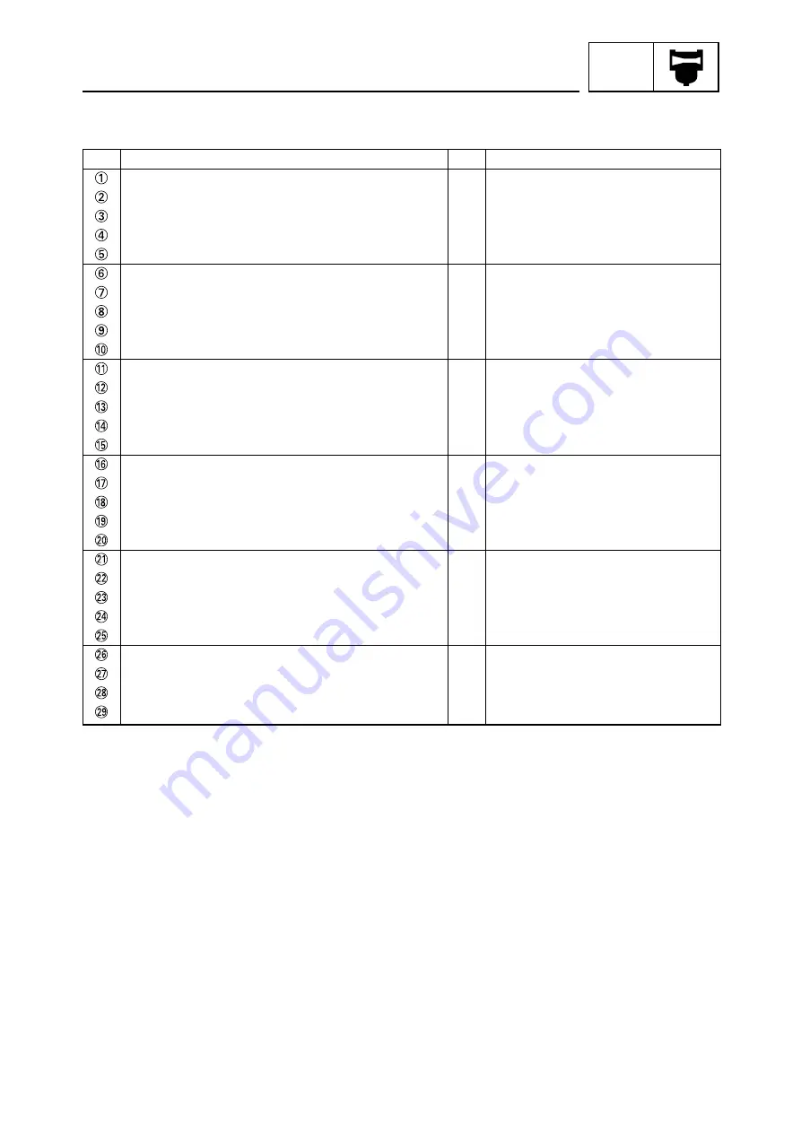
Order

Parts name

Q'ty

Remarks

Bolt 
Manifold 
Gasket 
Carburetor assembly 
Screw 
Pump cover 
Pump gasket 
Pump diaphragm 
Metering diaphragm gasket 
Diaphragm assembly 
Metering diaphragm cover 
Screw 
Inlet needle valve 
Metering lever pin 
Metering lever 
Spring 
Screw 
Spring 
Idle adjust screw 
Spring 
High speed needle 
Spring 
Idle speed needle 
Throttle shaft assembly 
Spring 
Throttle valve 
Screw 
Throttle stopper 
Screw


1

Summary of Contents for KT100SEC

Page 1: ...RACING KART OWNER S SERVICE MANUAL 7YP 28199 SE ...

Page 2: ...ocedures will be forwarded to all Authorized Yamaha dealers and will where applicable appear in future editions of this manual PARTICULARY IMPORTANT INFORMATION This material is distinguished by the following notation WARNING CAUTION Failure to follow WARNING instructions could result in severe injury or death to the racing kart operator a bystander or a person inspecting or repairing the racing k...

Page 3: ...maged 2 Remove Bolt crankcase CAUTION CAUTION CONSTRUCTION OF THIS MANUAL This manual consists of chapters for the main categories of subjects See Illustrated symbois 1st title 2nd title 3rd title MANUAL FORMAT All of the procedures in this manual are organized in a sequential step by step format The infor mation has been compiled to provide the mechanic with an easy to read handy reference that c...

Page 4: ...MENTS ENGINE CARBURETOR ELECTRICAL Special tool Oil capacity Lubricant Tightening Specified value Service limit Resistance Ω Voltage V Electric current A Engine speed Apply engine mixing oil Apply lightweight lithium soap base grease Apply locking agent LOCTITE R Use new one GEN INFO SPEC INSP ADJ ENG ELEC CARB ...

Page 5: ...INDEX GENERAL INFORMATION GEN INFO 1 SPECIFICATIONS SPEC 2 REGULAR INSPECTION AND ADJUSTMENTS 3 ENGINE ENG 4 ELECTRICAL ELEC 6 CARBURETOR CARB 5 INSP ADJ ...

Page 6: ... 4 5 REMOVING THE CLUTCH 4 6 REMOVING THE CRANKSHAFT 4 7 REMOVING THE BEARING 4 8 CHECKING THE ENGINE PARTS 4 9 CHECKING THE CYLINDER HEAD 4 9 CHECKING THE CYLINDER 4 10 CHECKING THE PISTON AND PISTON PIN 4 11 CHECKING THE PISTON RING 4 11 CHECKING THE PISTON CLEARANCE 4 12 CHECKING THE CLUTCH 4 13 CHECKING THE GEAR1 3 AND IDLE GEAR 4 14 CHECKING THE STARTER MOTOR GEAR 4 14 CHECKING THE CRANKSHAFT...

Page 7: ...CLUDED PARTS 1 Install Battery box 2 Install Battery 3 Connect Battery lead Install the switch stay between the steering wheel and its support INCLUDED PARTS SWITCH BRACKET INSTALLING THE BATTERY First connect the positive lead then the negative lead CAUTION 1 ...

Page 8: ...the engine comes to a stop 2 When the engine is cold cover the air box entrance lightly with the hand to choke off the air flow STARTING Do not crank the engine more than 4 seconds on any one attempt For the protection of the starter motor and the prevention of the battery s over discharge allow 30 seconds or more for engine restart If the engine is started in continued succession the battery may ...

Page 9: ...J Type Standard setting Idle needle High speed needle Electrical Ignition system Ignition system BTDC Coil Primary winding resistance Secondary winding resistance Spark plug Type manufacturer plug gap KT100SEC KT100SEJ Air cooled 2 stroke gasoline Single cylinder forward inclined 0 0976L 97 6cm3 52mm 46mm 7 9 Automatic Starter motor Assemble type Needle roller bearing A 0 1 mm or less B 0 03 mm or...

Page 10: ...eration voltage Rating Starter motor Type manufacturer Operation voltage Output Starter relay Type manufacturer Voltage rating Min operation voltage Open voltage Coil resistance GT7B 4 GS yuasa 12V 6 5Ah 5M05 289 Mitsuba 12V 0 3kw B768042 Jideco DC12V 30 min DC8 V or less DC4 V or less 4 4Ω ...

Page 11: ...diameter Pitch Q ty 6 1 8 4 5 2 4 1 4 2 2 1 1 1 2 5 2 0 Part to be tightened Tightening N m kg m Remarks Starter motor mounting bolt M6 1 0 10 16 1 0 1 6 Thread size Thread diameter Pitch Q ty 2 Thread size M 5 8 mm P0 8 M 6 10mm P1 0 M 8 13mm P1 25 M10 14mm P1 5 M12 17mm P1 5 Tightening 0 4kg m 0 6kg m 1 5kg m 3 0kg m 5 5kg m GENERAL TORQUE SPECIFICATIONS This chart specifies torque for standard ...

Page 12: ...NG DIAGRAM Starter relay Positive lead 1 battery starter relay Positive lead 2 starter relay starter motor Negative lead 1 battery coupler Negative lead 2 coupler starter motor Sub lead Starter switch Engine stop switch Fuel hose Throttle cable ...

Page 13: ...RING Inspect Replace CRANK Inspect Measure Replace CRANK PIN Inspect Replace CRANK BEARING Inspect Replace OIL SEAL Inspect Replace CYLINDER Inspect Measure Replace Carbon deposits Tightening 1 8 2 3kg m Carbon deposits Piston clearance Replace the piston as a set Replace the piston as a set Replace the piston as a set Signs of heat discoloration Replace the connecting rod as a set Free play exist...

Page 14: ...TS NUTS Inspect Replace GASKETS Replace SPARK PLUG Inspect Clean Replace PLUG CAP Inspect Replace TCI MAGNETO Inspect Primary winding resistance Secondary winding resistance Standard position Bend spring free length Contamination Dust Tightening 0 75 1 2kg m Gaskets o rings Never use using gaskets Insulator color Wear Damage Carbon deposits Damage Item Remarks After break in Every run Every race E...

Page 15: ...ll lean out the mixture at low speeds and turning out it will enrich the mixture 5 Adjust Idle adjust screw Turning in the idle adjust screw will increase idle speed and turning out it will decrease idle speed Standard idle needle screw position SEC 1 1 3 1 6 80 10 min SEJ 1 1 4 1 6 75 10 min Standard high speed needle screw position SEC 5 12 1 6 25 10 min SEJ 11 12 55 min Engine speed meter 90890...

Page 16: ...ecification Adjust 2 5mm ADJUSTING THE THROTTLE VALVE 1 Inspect Throttle valve Check whether the throttle valve is fully open when the throttle pedal is depressed for a full stroke 3 Adjust Throttle pedal free play Loosen the locknut and adjust the adjuster 2 Adjust Locknut Adjuster Loosen the locknut and adjust the adjuster After adjusting the throttle valve the throttle pedal should be adjusted ...

Page 17: ...austic sulfuric acid Therefore always follow these preventive measures Charge batteries in a well ventilated area Keep batteries away from fire sparks or open flames e g welding equipment lighted cigarettes DO NOT SMOKE when charging or handling batteries KEEP BATTERIES AND ELECTROLYTE OUT OF REACH OF CHILDREN Avoid bodily contact with electrolyte as it can cause severe burns or permanent eye inju...

Page 18: ... Tester negative probe Battery negative terminal Since MF batteries are sealed it is not possible to check the charge state of the battery by measuring the specific gravity of the electrolyte Therefore the charge of the battery has to be checked by measuring the voltage at the battery terminals NOTE First disconnect the negative battery lead and then the positive battery lead Digital circuit teste...

Page 19: ...age 12 0 V d Charging time 6 5 hours e Charge of the battery 20 30 refer to the appropriate charging method illustration Use the specified current and voltage for a refreshing charge The charge state of an MF battery can be checked by measuring its open circuit voltage i e the voltage when the positive terminal is disconnected No charging is necessary when the open circuit voltage equals or exceed...

Page 20: ... chance of sparks do not plug in the battery charger until the battery charger leads are connected to the battery Before removing the battery charger lead clips from the battery terminals be sure to turn off the battery charger Make sure the battery charger lead clips are in full contact with the battery terminal and that they are not shorted A corroded battery charger lead clip may generate heat ...

Page 21: ... Install Battery 8 Connect Battery lead to battery terminal 5 Inspect Battery terminal Dirt Clean with wire brush Loose Connect 6 Apply the grease Battery terminal First connect the positive lead then the negative lead CAUTION ...

Page 22: ...o not tighten the plug above the specified torque NOTE When the engine runs for many hours at low speeds the spark plug insulator will become sooty even if the engine and carburetor are in good operating condition NOTE Remove a mud and dust from the cylinder head before removing the spark plug NOTE Spark plug 1 5 2 5kg m Spark plug gap 0 6 0 7mm Standard spark plug B9EVX Manufacturer NGK Do not ru...

Page 23: ...direction 4 Set the dial gauge to zero at TDC 5 From TDC rotate the rotor clockwise until the dial gauge indicates that the piston is at 2 6 mm from TDC 6 Check Ignition timing Punch mark on rotor should be aligned with punch mark on stator Not aligned Adjust Spark plug 1 5 2 5kg m 1 From TDC rotate the rotor clockwise until the dial gauge indicates that the piston is at 2 6 mm from TDC 2 Loosen t...

Page 24: ... air gap between the rotor and coil assembly 3 Adjust Air gap Loosen the coil assembly mounting bolts and move the pick up coil assembly until the specified gap is obtained 4 Tighten Coil assembly mounting bolt 5 Install Stay1 Gear3 Crankcase cover2 Standard air gap 0 4mm Out of specification Adjust ...

Page 25: ... ENGINE Cylinder head Cylinder head gasket Spark plug Cylinder Cylinder gasket Crank assembly Bearing Oil seal Small end bearing Piston pin Piston Piston ring Piston pin clip Crankcase L R Joint pipe Drive sprocket Nut Absorber A Absorber B 4 ...

Page 26: ... Rotor Coil assembly Nut Plate Engine starter switch Engine stop switch Lead wire STARTER MOTOR Crankcase cover1 Crankcase cover2 Starter motor Idle gear Needle bearing Gear1 Needle bearing Bearing Gear3 Stay1 T R T R T R T R T R T R T R ...

Page 27: ...SL CLUTCH ASSY Circlip seeger ring Spacer Sprocket Z10 Sprocket Z11 M5 screw Clutch drum Roller gauge M8 stopper screw stop dowel Stud bolt adapter shaft Thrust washer shim Clutch body Key woodruff key Clutch cover Chain guard ...

Page 28: ...r mounting nut Cylinder Cylinder gasket REMOVING THE CYLINDER HEAD AND CYLINDER Piston pin puller 90890 01304 Before removing piston pin clip cover crankcase with a clean rag to prevent piston pin clip from falling into crankcase cavity Before removing the piston pin deburr the clip groove and pin hole area If the piston pin groove is deburred and piston pin is still difficult to remove use the pi...

Page 29: ... Crankcase cover2 mounting bolt Crankcase cover2 REMOVING THE TCI MAGNETO 1 Remove Rotor nut 2 Remove Stay1 mounting bolt Stay1 Gear3 mounting bolt Gear3 Gear1 Idle gear 3 Remove Crankcase cover1 mounting bolt Crankcase cover1 Starter motor mounting bolt Starter motor Take care not to scratch the piston or damage the piston ring by expanding it more than necessary CAUTION ...

Page 30: ...ove Circlip seeger ring Spacer 3 Remove Roller gauge Thrust washer shim 2 Remove Clutch drum 2 Remove Rotor When removing the rotor use the rotor puller Rotor puller 90890 01362 Take care not to screw in the two bolts of the rotor puller too far They may contact the stator and damage it CAUTION ...

Page 31: ...E 4 Loosen M8 stopper screw stop dowel Stud bolt adapter shaft REMOVING THE CRANKSHAFT 1 Remove Engine bracket mounting bolt Engine bracket 5 Remove Clutch body Reference For removal use the specialized tool 6 Remove Key woodruff key ...

Page 32: ...e one depending on how the bearing is installed Fixed on the outside Bearing puller Fixed on the inside Bearing puller 4 Remove Left crankcase Crankshaft assembly Make sure the crank separating tool body is parallel with the crankcase Crankcase separating tool 90890 01135 Take care so that the oil seal lip is not damaged Crankcase separating tool 90890 01135 Take care so that the oil seal lip is n...

Page 33: ...NE PARTS CHECKING THE ENGINE PARTS CHECKING THE CYLINDER HEAD 1 Inspect Carbon deposits Use a rounded scraper Avoid scratching the aluminum Warp limit 0 015mm 2 Measure Cylinder head warpage Out of specification Replace CAUTION ...

Page 34: ...Inspect Cylinder wall Score marks Repair Use 400 600 grit wet sandpaper Damage Rebore or Replace 3 Measure Cylinder wall wear Measure the cylinder bore in parallel to and at right angles to the crankshaft Then find the average of the measurements Out of specification Rebore or replace Cylinder wall wear Maximum Aa Cb Minimum Aa Cb Cylinder bore gauge 90890 03017 CAUTION ...

Page 35: ...Insert a ring into the cylinder and push it approximately 10 mm 0 39 in into the cylinder CHECKING THE PISTON RING Standard piston diameter 51 970 51 990mm End gap limit 0 5mm 3 Check Free play When the piston pin is in place in the piston There should be no noticeable for the play Free play exists Replace piston pin and or piston 4 Inspect Check the free play when the piston pin and bearing are i...

Page 36: ...ND PISTON PIN CHECKING THE PISTON CLEARANCE If out of specification rebore or replace cylinder and replace piston and piston rings as a set If the piston clearance is over specification rebore cylinder and replace piston with oversized piston to meet the specification If piston is replaced with oversized piston piston ring should be replaced with the equivalent oversized piston ring Standard pisto...

Page 37: ...dy Wear Scratch Damage Replace 2 Inspect Drive sprocket Wear Damage Replace the clutch drum CHECKING THE CLUTCH 4 Inspect the other parts Wear Damage Replace Standard shoe thickness 3 3mm Wear limit 1mm 3 Inspect Clutch shoe thickness Roller gauge Wear Damage Replace ...

Page 38: ...epair or replace Crank width Out of specification Repair or replace CHECKING THE CRANKCASE BEARING 1 Inspect Crankshaft bearing Rough spot seizure Replace Standard 45 8 45 9mm Small end free play Runout Crank width Limit 1 0mm 0 03mm CHECKING THE GEAR1 3 AND IDLE GEAR 1 Inspect Gear1 Gear3 Idle gear Wear Damage Replace CHECKING THE STARTER MOTOR GEAR 1 Inspect Starter motor gear Wear Damage Replac...

Page 39: ...ENG CHECKING THE ENGINE PARTS CHECKING THE CRANKCASE OIL SEAL 1 Inspect Oil seal Wear Damage Replace CHECKING THE CRANKCASE 1 Inspect Right crankcase Left crankcase Wear Repair Use 400 600 grit wet sandpaper ...

Page 40: ...tall Crankshaft bearing Install the bearing by pressing it on the side having the manufacture s marks or numbers Install the oil seal by pressing its outer race parallel 2 Install Oil seal Install the bearing with its outer race 0 5mm above the crank case surface NOTE Oil seal CAUTION ...

Page 41: ...before applying the sealant 2 Install Dowel pin Take care so that the oil seal lip is not damaged 3 Install Right crankcase Crankshaft Install the crankshaft by installing tools 4 Apply the sealant Left crankcase Crankshaft installing pot 90890 01274 Crankshaft installing bolt 90890 01275 Adapter 90890 01278 CAUTION ...

Page 42: ...r smooth movement Take care not to scratch the piston or damage the piston ring 2 Install Small end bearing Apply the engine oil onto the small end and big end bearings 5 Install Crankcase mounting bolt Tighten all bolts in 2 3 steps and be sure to tighten in numbered order as shown Crankcase mounting bolt 1 0 1 6kg m 6 Install Engine bracket Engine bracket mounting bolt 2 5 3 0kg m CAUTION ...

Page 43: ...the crankcase with a clean rag to prevent the piston pin clip from falling into the crankcase cavity Never force to insert NOTE Apply the engine oil onto the cylinder inner surface Make sure the piston ring is properly positioned Install the cylinder with one hand while compressing the piston ring with the other hand After installing check the smooth movement of the piston NOTE Piston pin clip 2 I...

Page 44: ...order as shown 4 Install Cylinder head 6 Temporarily install Coil assembly 7 Adjust the air gap and tighten the coil assembly Cylinder head 1 8 2 3kg m INSTALLING THE STARTER MOTOR 1 Install the starter motor to the crankcase cover1 Starter motor mounting bolt Starter motor 2 Install Crankcase cover1 mounting bolt Crankcase cover1 3 Install Rotor nut 4 Adjust the ignition timing Refer to the CHAPT...

Page 45: ...ng agent LOCTITE R 2 Install Clutch body Install the clutch body while taking note of its direction 2 Install Stay1 mounting bolt Stay1 Gear3 mounting bolt Gear3 Gear1 Idle gear 3 Install Crankcase cover2 mounting bolt Crankcase cover Stud bolt adapter shaft 2 5kg m Reference For installation use the specialized tool CAUTION ...

Page 46: ...pply locking agent LOCTITE R 6 Install Clutch drum 7 Install Spacer Circlip seeger ring After installing the clutch drum check for smooth movement M8 stopper screw stop dowel 2 0kg m 5 Tighten Thrust washer shim Roller gauge Apply the grease onto the roller gauge CAUTION ...

Page 47: ...4 23 ENG ...

Page 48: ...5 1 CARB CARBURETOR Preparation for removal Remove the air box Remove the throttle cable Remove the fuel hose Remove the pulse hose REMOVING AND DISASSEMBLY THE CARBURETOR ...

Page 49: ...ew Circuit plate Diaphragm Gasket Screw Pin Metering lever Spring Inlet needle valve Screw Cover Gasket Pump diaphragm High speed needle Spring Washer O ring Idle needle Spring Ring Screw Throttle valve Throttle shaft Spring Screw Choke valve Choke shaft 2 2 1 1 1 1 4 1 1 1 2 1 1 1 1 1 1 1 1 4 1 1 1 1 1 1 1 1 1 1 1 1 1 1 1 1 1 REMOVING THE CARBURETOR REMOVING THE INLET NEEDLE VALVE REMOVING THE ME...

Page 50: ...5 3 CARB SL CARBURETOR Preparation for removal Remove the air box Remove the throttle cable Remove the fuel hose Remove the pulse hose REMOVING AND DISASSEMBLY THE SL CARBURETOR ...

Page 51: ...p gasket Pump diaphragm Metering diaphragm gasket Diaphragm assembly Metering diaphragm cover Screw Inlet needle valve Metering lever pin Metering lever Spring Screw Spring Idle adjust screw Spring High speed needle Spring Idle speed needle Throttle shaft assembly Spring Throttle valve Screw Throttle stopper Screw 2 1 1 1 1 1 1 1 1 1 1 4 1 1 1 1 1 1 1 1 1 1 1 1 1 1 1 1 1 ...

Page 52: ...rburetor Plug the fuel hose so that fuel does not run out 1 Inspect Float chamber body Blow out all passages and jets with compressed air CHECKING THE CARBURETOR Never use a wire 1 Inspect Metering lever distance 2 Adjust Metering lever Bend the rib of the metering lever ASSEMBLING THE CARBURETOR Standard metering lever distance 0 13 0 25mm Out of specification Adjust WARNING CAUTION ...

Page 53: ...B CARBURETOR 1 Install Carburetor Air box Hose clamp INSTALLING THE CARBURETOR 2 Connect Throttle cable Fuel hose Negative pressure hose 3 Adjust Throttle pedal free play Engine idling speed Carburetor gasket ...

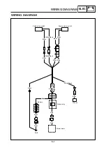
Page 54: ...WIRING DIAGRAM Engine stop switch Engine starter switch Starter relay TCI unit Starter motor Battery Red Red Red Black White Black Black Blue Black White Black Black Black Earth White Black Black Red Red Blue Black Black Black ...

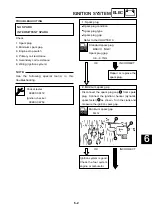
Page 55: ... Ignition checker 90890 06754 Spark plug condition Spark plug type Spark plug gap Refer to the CHAPTER 3 Repair or replace the spark plug 1 Spark plug OK INCORRECT Standard spark plug B9EVX NGK Spark plug gap 0 6 0 7mm Disconnect the spark plug cap from spark plug Connect the ignition checker dynamic spark tester as shown Turn the crank and measure the ignition spark gap Ignition system is good Ch...

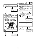
Page 56: ... resistance 0 8 1 0 Ω 1Ω Replace the ignition coil 5 Secondary coil resistance OK NO Disconnect the high tension lead from the spark plug Disconnect the spark plug cap from the high tension lead Connect the pocket tester x1kΩ to the ignition coil Tester lead Black terminal Tester lead High tension lead Secondary coil resistance 10k Ω kΩ Replace the ignition coil Replace the rotor Properly connect ...

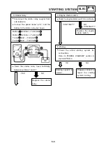
Page 57: ...rge or replace the battery 1 Battery OK NO Open circuit voltage 12 8 V or more at 20 C Connect the positive battery terminal and starter motor lead with a jumper lead Dose the starter motor turn Repair or replace the starter motor 2 Starter motor YES NO A wire that is used as a jumper lead must have at least the same capacity or more as that of the battery lead otherwise the jumper lead may burn T...

Page 58: ...ery terminal Terminal2 Battery terminal Terminal4 Tester lead Terminal1 Tester lead Terminal3 Replace the starter relay Check the entire starting system for connections Refer to WIRING DIAGRAM section in the CHAPTER 6 5 Wiring OK NO Starting system is correct 12V Check the engine starter switch for continuity 4 Engine starter switch Replace the engine starter switch CONTINUITY NO CONTINUITY Proper...

Page 59: ......

Page 60: ...PRINTED IN JAPAN E PRINTED ON RECYCLED PAPER YAMAHA MOTOR CO LTD ...

Reviews: