background image

English

10

HS80M/HS50M/HS10W  Owner’s Manual

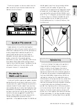
100° and 120°, as shown in the diagram above. The center speaker should be placed precisely midway between the main 

front speakers, at the same distance from the listening position as the other speakers (which means that ideally it will be a bit 

behind the main left and right speakers.

As you may have deduced by now, the main left and right, center, and rear speakers are all located on the circumference 

of a circle with its center at the listening position. An easy way to get all the distances right is to use a piece of string cut or 

marked to the exact distance between the main left and right speakers. Attach the string to a mic stand or other convenient 

object at the listening position and use it to measure the distance from the listening position to each of the speakers. 

Stretched from the listening position to the speaker position the string will also provide a convenient guide for aligning the 

speakers so that they point directly at the listening position.

MG-series Mixer Setup

If you’re connecting to a standard mixer that is not specifically 

designed for surround production, your main L and R speakers 

can be connected to any convenient stereo output pair via the 

HS10W subwoofer, while the center and rear speakers will be 

connected to individual output channels.

Example: MG16/6FX

Digital Mixer Setup

If you’re connecting your HS-series speakers to a mixing console 

that features built-in surround handling capability — such as the 

Yamaha DM2000, DM1000, or 02R96 — each speaker will be 

connected directly to the console output dedicated to handling 

that particular surround channel. In this type of setup you can take 

full advantage of the console’s advanced surround mixing and bass 

management facilities.

DVD 

Player

Input Channel

Output

Connector

Speaker

L

Ch1 (ST=ON, PAN 

 L)

ST OUT (L)

L

R

Ch2 (ST=ON, PAN 

 R)

ST OUT (R)

R

LS

Ch3 (GRP1-2, PAN 

 L)

GROUP OUT 1(L)

LS

RS

Ch4 (GRP1-2, PAN 

 R)

GROUP OUT 2(R)

RS

C

Ch5 (GRP3-4, PAN 

 L)

GROUP OUT 3

C

LFE

Ch6 (ST=ON, PAN

Center,

Fader

+10 dB Boost)

ST OUT

LFE

DVD Player 

6 Channel Line

LS

RS

LFE

R

L

C

OMNI Out

LS

RS

R

LFE

C

L

Summary of Contents for HS10W

Page 1: ...EN DE FR ES ZH JA Powered Near field Reference Monitors Subwoofer OWNER S MANUAL BEDIENUNGSANLEITUNG MODE D EMPLOI MANUAL DE INSTRUCCIONES 取扱説明書 ...

Page 2: ...when moving the cart apparatus combination to avoid injury from tip over 13 Unplug this apparatus during lightning storms or when unused for long periods of time 14 Refer all servicing to qualified service personnel Servicing is required when the apparatus has been damaged in any way such as power supply cord or plug is damaged liquid has been spilled or objects have fallen into the apparatus the ...

Page 3: ...rvez le en lieu sûr pour pouvoir vous y référer ultérieurement Gracias por elegir los monitores o el subwoofer autoamplificados de Yamaha A fin de aprovechar al máximo las características de los altavoces y obtener un rendimiento y durabilidad óptimos lea atentamente este manual antes de utilizar el sistema Guarde este manual en un lugar seguro para futuras consultas このたびは ヤマハ製品をお買い求めいただきまして まことにあ...

Page 4: ...erheating possibly causing damage to the device s or even fire Do not expose the device to excessive dust or vibrations or extreme cold or heat such as in direct sunlight near a heater or in a car during the day to prevent the possibility of panel disfiguration or damage to the internal components Do not place the device in an unstable position where it might accidentally fall over Before connecti...

Page 5: ...dary Yamaha NS10M became a standard monitor in the music and sound industry and is still in use in many studios throughout the world for precisely that reason it offered flat response and excellent resolution that allowed engineers and producers to hear subtle details that make the difference between good and great sound The HS series monitors carry on the tradition with accuracy and detail that c...

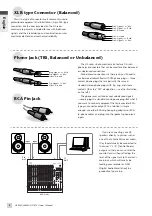
Page 6: ...the TRS designation see the illustration on the left The phone jacks will also accept unbalanced signals simply plug in a standard mono phone plug But what if you want to connect equipment that only provides RCA type pin connector outputs The solution is simple enough use either RCA to phone plug adaptors or RCA to phone cables and plug into the speaker s phone jack inputs If you re connecting you...

Page 7: ...tally or use some equalization will probably be required The HS50M and HS80M speakers make this easy by providing a ROOM CONTROL switch that modifies the speaker s bass characteristics to compensate for the exaggeration caused by nearby walls As your speakers get closer to the walls you might find that setting the ROOM CONTROL switch to the 2 or 4 setting gives you more natural response in the bas...

Page 8: ... are the most directional Fine tuning for Stereo The speaker LEVEL controls should be set to the same level A setting of about 12 o clock corresponds to a nominal input level of about 4 dB Since no subwoofer is being used in this setup set the LOW CUT switch to FLAT When set to 2 dB the EQ MID switch attenuates the midrange frequencies slightly to produce a somewhat softer sound that may be better...

Page 9: ...ion which corresponds to a HPF frequency of about 100 Hz The HIGH CUT frequency can be adjusted later to achieve the smoothest integration with the HS50M or HS80M speakers Turn the HS10W LOW CUT switch ON Adjust the LOW CUT control to achieve the desired degree of bass extension Set the HS50M HS80M LOW CUT switch to FLAT When set to 2 dB the HS50M HS80M EQ MID switch attenuates the midrange freque...

Page 10: ... speakers so that they point directly at the listening position MG series Mixer Setup If you re connecting to a standard mixer that is not specifically designed for surround production your main L and R speakers can be connected to any convenient stereo output pair via the HS10W subwoofer while the center and rear speakers will be connected to individual output channels Example MG16 6FX Digital Mi...

Page 11: ...too bright Maintain a Consistent Monitoring Level Another difference between listening and monitoring is that when you re listening for enjoyment you probably listen at significantly different levels at different times from soft and unobtrusive for background music right though room shaking for involved listening or dancing This is definitely not the case for serious monitoring The response of you...

Page 12: ...setting the range below 500 Hz is cut by 4 dB HIGH TRIM switch Adjusts the level of high frequency range HS50M Setting the switch to the 0 position produces a flat frequency response With the 2 dB setting the range above 3 kHz is boosted by 2 dB With the 2 dB setting the range above 3 kHz is cut by 2 dB HS80M Setting the switch to the 0 position produces a flat frequency response With the 2 dB set...

Page 13: ... low frequency is cut Use the LOW CUT control to set the cutoff frequency from 80 Hz to 120 Hz LOW CUT switch If the LOW CUT switch is on the low frequencies of the signal from the OUTPUT connector is cut Use the LOW CUT control to set the cutoff frequency from 80 Hz to 120 Hz LOW CUT control Use the LOW CUT control to set the cutoff frequency from 80 Hz to 120 Hz when the LOW CUT switch is on HIG...

Page 14: ...Amp Unit Output Power Total 70 W dynamic power LF 45 W 4 ohms HF 25 W 8 ohms Total 120 W dynamic power LF 75 W 4 ohms HF 45 W 8 ohms 150 W 4 ohms dynamic power Input Sensitivity Impedance 10 dBu 10 k ohms 10 dBu 10 k ohms 10 dBu 10 k ohms Output Sensitivity Impedance 10 dBu 600 ohms Input Connectors parallel 1 XLR 3 31 type balanced 2 PHONE balanced 1 XLR 3 31 type balanced 2 PHONE balanced 1 XLR ...

Page 15: ...EQUENCY Hz HS50M HS80M MID EQ INPUT 1 HIGH CUT LIMITER HIGH TRIM INPUT 2 LF HF LEVEL LOW CUT ROOM CONTROL LOW BOOST LOW CUT STEP FILTER P AMP STEP FILTER LOWCUT P AMP INPUT OUTPUT LOW CUT OUTPUT R ch L ch EXTSUB OUT LOW CUT ON OFF SUM SPEAKER PHASE NORMAL REVERSE LEVEL P AMP INPUT INPUT INPUT LOW CUT HIGH CUT LIMITTER HS10W HS10W 386 15 3 16 300 11 13 16 350 13 3 4 Unit mm inch Block Diagram Perfo...

Page 16: ... Yamaha Scandinavia AB Grini Næringspark 1 N 1345 Østerås Norway Tel 67 16 77 70 OTHER EUROPEAN COUNTRIES Yamaha Music Central Europe GmbH Siemensstraße 22 34 25462 Rellingen Germany Tel 49 4101 3030 Yamaha Corporation Asia Pacific Music Marketing Group Nakazawa cho 10 1 Hamamatsu Japan 430 8650 Tel 81 53 460 2313 TURKEY CYPRUS Yamaha Music Central Europe GmbH Siemensstraße 22 34 25462 Rellingen G...

Reviews: