background image

8-37

8

NOTE:

The wheels need to be removed to check the
brake pads. (See page 8-52.)

EBU24221

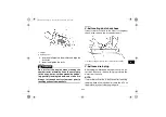
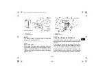
Rear brake pads

Check each rear brake pad for damage and mea-
sure the lining thickness. If a brake pad is dam-
aged or if the lining thickness is less than 1.5 mm
(0.06 in), have a Yamaha dealer replace the brake
pads as a set.

EBU24261

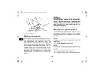
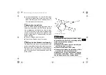
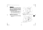
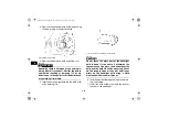
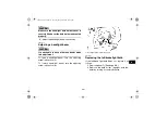
Checking the brake fluid level 

Insufficient brake fluid may allow air to enter the
brake system, possibly causing it to become inef-
fective.
Before riding, check that the brake fluid is above
the minimum level mark and replenish if neces-
sary. A low brake fluid level may indicate worn
brake pads and/or brake system leakage. If the
brake fluid level is low, be sure to check the brake
pads for wear and the brake system for leakage.

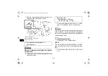
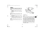
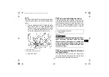
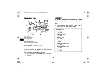
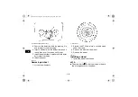
1. Brake pad
2. Lining thickness

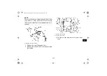
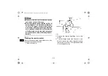
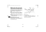
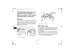
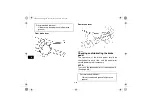
1. Brake pad
2. Lining thickness

U2C661E0.book  Page 37  Thursday, March 16, 2006  10:45 AM

Summary of Contents for GRIZZLY 660 YFM66FGW

Page 1: ...YFM66FGW 2C6 28199 61 OWNER S MANUAL MANUEL DU PROPRIÉTAIRE MANUAL DEL PROPIETARIO ...

Page 2: ...PRINTED IN JAPAN 2006 03 0 5 1 CR E F S PRINTED ON RECYCLED PAPER IMPRIMÉ SUR PAPIER RECYCLÉ IMPRESO EN PAPEL RECICLADO YAMAHA MOTOR CO LTD ...

Page 3: ...OWNER S MANUAL YFM66FGW 2C6 28199 61 E0 U2C661E0 book Page 1 Thursday March 16 2006 10 45 AM ...

Page 4: ...er relevant EEC Directives 89 336 EEC Title and or number and date of issue of the other EEC Directives if applicable To effect correct application of the essential health and safety requirements stated in the EEC Directives the following standards and or technical specifications were consulted Title and or number and date of issue of standards and or specifications NL 1119 NC Schiphol Place and d...

Page 5: ...operation of this ATV This manual includes important safety information It provides information about special tech niques and skills necessary to ride the ATV It also includes basic maintenance and inspection proce dures If you have any questions regarding the operation or maintenance of your ATV please consult a Yamaha dealer AN IMPORTANT SAFETY MESSAGE READ THIS MANUAL COMPLETELY BEFORE OPERATIN...

Page 6: ...hange without notice The Safety Alert Symbol means ATTENTION BECOME ALERT YOUR SAFETY IS INVOLVED Failure to follow WARNING instructions could result in severe injury or death to the ATV operator a bystander or a person inspecting or repairing the ATV A CAUTION indicates special precautions that must be taken to avoid damage to the ATV A NOTE provides key information to make procedures easier or c...

Page 7: ...ce paved street paved road or motorway Please check your local riding laws and regulations before operating this ATV EBU17390 YFM66FGW OWNER S MANUAL 2006 by Yamaha Motor Co Ltd 1st edition March 2006 All rights reserved Any reprinting or unauthorized use without the written permission of Yamaha Motor Co Ltd is expressly prohibited Printed in Japan U2C661E0 book Page 1 Thursday March 16 2006 10 45...

Page 8: ...13 Drive select lever 4 14 Recoil starter 4 14 Fuel tank cap 4 14 Fuel 4 15 Fuel cock 4 16 Starter choke 4 17 Seat 4 18 Storage compartment 4 19 Front carrier 4 20 Rear carrier 4 20 Adjusting the front and rear shock absorber assemblies 4 20 Auxiliary DC jack 4 21 PRE OPERATION CHECKS 5 1 Pre operation check list 5 1 Fuel 5 3 Engine oil 5 3 Final gear oil 5 3 Differential gear oil 5 3 Coolant 5 3 ...

Page 9: ...er s manual and tool kit 8 1 Periodic maintenance and lubrication chart 8 3 Removing and installing panels 8 8 Checking the spark plug 8 15 Engine oil and oil filter cartridge 8 17 Changing the final gear oil 8 21 Differential gear oil 8 22 Coolant 8 24 Cleaning the air filter element 8 28 Cleaning the spark arrester 8 32 V belt cooling duct check hose 8 33 V belt case drain plug 8 33 Adjusting th...

Page 10: ...al joint 8 45 Checking the stabilizer bushes 8 45 Lubricating the upper and lower arm pivots 8 45 Lubricating the knuckle pivots 8 45 Battery 8 46 Replacing a fuse 8 48 Replacing a headlight bulb 8 49 Adjusting a headlight beam 8 51 Replacing the tail brake light bulb 8 51 Removing a wheel 8 52 Installing a wheel 8 52 Troubleshooting 8 54 Troubleshooting charts 8 55 CLEANING AND STORAGE 9 1 Cleani...

Page 11: ...ild if he or she does not have the abilities to operate it safely Never carry a passenger on an ATV Always avoid operating an ATV on any paved surfaces including sidewalks driveways park ing lots and paved streets Never operate an ATV on any paved street paved road or motorway Watch carefully for other vehicles when operat ing on unpaved public streets or roads Make sure you know your country s la...

Page 12: ...bing hills as described in this manual Check the ter rain carefully before you start up any hill Never climb hills with excessively slippery or loose sur faces Shift your weight forward Never open the throttle suddenly Never go over the top of a hill at high speed Always follow proper procedures for going down hills and for braking on hills as described in this manual Check the terrain carefully b...

Page 13: ...al Remember that wet brakes may have reduced stopping ability Test your brakes after leaving water If necessary apply them several times to let friction dry out the linings Always be sure there are no obstacles or people behind you when you operate in reverse When it is safe to proceed in reverse go slowly Always use the size and type of tires specified in this manual Always maintain proper tire p...

Page 14: ...s If you should swal low some gasoline or inhale a lot of gasoline vapor or get some gasoline in your eyes seek medical help immediately If gasoline spills on your skin wash with soap and wa ter If gasoline spills on your clothing change your clothes WARNING EWB00070 Always operate your ATV in an area with ade quate ventilation Never start or run the engine in a closed area Exhaust fumes are poiso...

Page 15: ...2 1 2 EBU17660 LOCATION OF THE WARNING AND SPECIFICATION LABELS U2C661E0 book Page 1 Thursday March 16 2006 10 45 AM ...

Page 16: ...s contain important information for safe and proper operation Never remove any labels from your ATV If a label becomes difficult to read or comes off request a replace ment label from your Yamaha dealer For Europe and Oceania U2C661E0 book Page 2 Thursday March 16 2006 10 45 AM ...

Page 17: ...2 3 2 For Europe U2C661E0 book Page 3 Thursday March 16 2006 10 45 AM ...

Page 18: ...2 4 2 For Europe U2C661E0 book Page 4 Thursday March 16 2006 10 45 AM ...

Page 19: ...2 5 2 For Europe U2C661E0 book Page 5 Thursday March 16 2006 10 45 AM ...

Page 20: ...2 6 2 For Oceania U2C661E0 book Page 6 Thursday March 16 2006 10 45 AM ...

Page 21: ...2 7 2 For Oceania U2C661E0 book Page 7 Thursday March 16 2006 10 45 AM ...

Page 22: ... select lever box check hose 11 V belt cooling duct check hose 1 Rear shock absorber assembly spring preload adjusting ring 2 Spark arrester 3 Storage compartment and tool kit 4 Battery 5 Air filter case 6 Spark plug 7 Front brake fluid reservoir 8 Front shock absorber assembly spring preload adjusting ring 9 Rear brake fluid reservoir 10 Brake pedal 11 V belt case drain plug U2C661E0 book Page 1 ...

Page 23: ...n this manual 1 Drive select lever 2 Rear brake lever 3 Handlebar switches 4 Horn switch 5 Starter choke 6 Multifunction meter unit 7 Main switch 8 On Command four wheel drive differential gear lock switch 9 Throttle lever 10 Front brake lever 11 Auxiliary DC jack U2C661E0 book Page 2 Thursday March 16 2006 10 45 AM ...

Page 24: ...as follows ON All electrical systems are supplied with power The headlights and taillight come on when the light switch is on and the engine can be started The key cannot be removed OFF All electrical systems are off The key can be re moved 1 Main switch U2C661E0 book Page 1 Thursday March 16 2006 10 45 AM ...

Page 25: ...rs during operation stop the engine as soon as it is safe to do so and allow it to cool down for about 10 minutes CAUTION ECB00010 The engine may overheat if the ATV is over loaded In this case reduce the load to spec ification Start the engine after making sure that the warning light is out Continuous use while the warning light is on may cause damage to the engine 1 On Command differential gear ...

Page 26: ...fferential gear is locked EBU17970 Park indicator light This indicator light comes on when the transmis sion is in the park position EBU17980 High range indicator light This indicator light comes on when the transmis sion is in the high range position EBU17990 Low range indicator light This indicator light comes on when the transmis sion is in the low range position EBU18001 On Command differentia...

Page 27: ...de ODO and the tripmeter modes A and B in the following order ODO TRIP A TRIP B ODO To reset a tripmeter select it by pushing the TRIP ODO button and then push the TRIP ODO button for at least three seconds The tripmeters can be used to estimate the distance that can be traveled with a full tank of fuel This in formation will enable you to plan future fuel stops NOTE Holding in the TRIP ODO button...

Page 28: ...minutes by pushing the M button 5 Push the button and then release it to start the clock Fuel meter The fuel meter indicates the amount of fuel in the fuel tank The display segments of the fuel meter disappear from F full towards E empty as the fuel level decreases When the E segment disap pears and the fuel level warning indicator flashes set the fuel cock to reserve and refuel as soon as possibl...

Page 29: ...he engine EBU18151 Light switch OFF Set this switch to to turn on the low beams and the taillight Set the switch to to turn on the high beams and the taillight Set the switch to OFF to turn off all the lights CAUTION ECB00040 Do not use the headlights with the engine turned off for an extended period of time oth erwise the battery may discharge to the point that the starter motor will not operate ...

Page 30: ...ar as shown in the figure NOTE If the digits of the speedometer appear as shown when the switch is NOT being pushed this could indicate a malfunction in the electrical system In this case take the ATV to a Yamaha dealer at the first opportunity WARNING EWB00150 Always ride at a slow speed when the ATV is in four wheel drive differential gear lock and al low extra time and distance for maneuvers Al...

Page 31: ...d push the switch in to the 4WD position Then the four wheel drive indica tor comes on in the multifunction meter unit display To change from four wheel drive to two wheel drive stop the ATV and push the switch in to the 2WD position WARNING EWB00161 Always stop the ATV before changing from two wheel drive to four wheel drive and vice versa The ATV handles differently in two wheel drive than in fo...

Page 32: ...heels turn at the same speed To lock the differential gear in four wheel drive make sure the On Command four wheel drive switch is pushed in to the 4WD position Stop the ATV move the differential gear lock lever to position a and then push the differential gear lock switch in to the LOCK position When the dif ferential gear is locked the differential gear lock in dicator DIFF LOCK will come on alo...

Page 33: ... Always ride at a slow speed when the ATV is in differential gear lock and allow extra time and distance for maneuvers All wheels turn at the same speed when the dif ferential gear is locked so it takes more effort to turn the ATV The effort needed to turn in creases with the riding speed You may lose control and have an accident if you cannot make a sharp enough turn for the speed you are traveli...

Page 34: ...increase the engine speed Regulate the speed of the ATV by varying the throttle position Because the throttle is spring loaded the ATV will decelerate and the engine will return to an idle any time the hand is removed from the throttle lever Before starting the engine check the throttle to be sure it is operating smoothly Make sure it returns to the idle position as soon as the lever is released W...

Page 35: ...en the locknut WARNING EWB00240 Improper adjustment of the speed limiter and throttle could cause throttle cable damage or improper throttle operation You could lose control have an accident or be injured Do not turn the adjusting screw out more than 12 mm 0 47 in or the throttle cable could be dam aged Always make sure the throttle lever free play is adjusted to 3 0 5 0 mm 0 12 0 20 in See page 8...

Page 36: ...ght side of the ATV and the rear brake lever is located on the left handlebar To apply the rear brake push down on the brake pedal or pull the brake lever toward the handlebar grip 1 Front brake lever 1 Brake pedal 1 Rear brake lever U2C661E0 book Page 13 Thursday March 16 2006 10 45 AM ...

Page 37: ... Firmly grasp the handle and pull slightly until en gagement can be felt Then pull forcefully being careful not to pull the rope all the way out WARNING EWB00330 Always shift the drive select lever to park posi tion before starting the engine otherwise the ATV could start to move unexpectedly which could cause an accident EBU18720 Fuel tank cap Remove the fuel tank cap by turning it counter clockw...

Page 38: ... Fuel tank cap 1 Fuel level 2 Fuel tank filler tube Recommended fuel UNLEADED GASOLINE ONLY For Europe Regular unleaded gasoline only with a research octane number of 91 or high er Fuel tank capacity 20 0 L 5 28 US gal 4 40 Imp gal Fuel reserve amount 3 5 L 0 92 US gal 0 77 Imp gal U2C661E0 book Page 15 Thursday March 16 2006 10 45 AM ...

Page 39: ... to spill fuel especially on the engine or exhaust pipe which can cause a fire and severe injury Wipe up any spilled fuel immediately Do not refuel right after the engine has been running and is still very hot Be sure the fuel tank cap is closed securely EBU18820 Fuel cock The fuel cock supplies fuel from the tank to the car buretor while also filtering it The fuel cock lever positions are explain...

Page 40: ...n the fuel cock lever to this position if you run out of fuel while riding When this occurs refuel as soon as possible and be sure to turn the fuel cock lever back to ON EBU18850 Starter choke Starting a cold engine requires a richer air fuel mix ture which is supplied by the starter choke Move the starter choke in direction a to turn on the starter choke 1 Arrow mark pointing to ON 1 Arrow mark p...

Page 41: ...eat To remove the seat Pull the seat lock lever upward and pull up the seat at the rear To install the seat Insert the projections on the front of the seat into the seat holders and push down on the seat at the rear NOTE Make sure that the seat is securely fitted 1 Starter choke 1 Seat 2 Seat lock lever U2C661E0 book Page 18 Thursday March 16 2006 10 45 AM ...

Page 42: ...et any water enter the storage compartment CAUTION ECB00130 Do not store metal or sharply edged objects like tools in the storage compartment If they must be stored wrap them in appropriate cushion material to prevent damaging the stor age compartment Do not exceed the load limit of 2 0 kg 4 lb for the storage compartment Do not exceed the maximum load of 220 0 kg 485 lb for the ATV 1 Projection 2...

Page 43: ...preload can be adjusted to suit the rid er s weight and the riding conditions NOTE The rear wheels need to be removed to adjust the rear shock absorber assemblies See page 8 52 Adjust the spring preload as follows Turn the adjusting ring in direction a to increase the spring preload and thereby harden the suspen sion and in direction b to decrease the spring preload and thereby soften the suspensi...

Page 44: ...ocated at the front right side of the ATV The auxiliary DC jack can be used for suitable work lights radios etc The auxiliary DC jack should only be used when the engine is running 1 Set the light switch to OFF 2 Start the engine See page 6 1 3 Open the auxiliary DC jack cap and then in sert the accessory power plug into the jack 1 Special wrench Spring preload setting Minimum soft 1 Standard 2 Ma...

Page 45: ...es are used without the engine running or with the headlights turned on the battery will lose its charge and engine start ing may become difficult Do not use an automotive cigarette lighter or other accessories with a plug that gets hot because the jack can be damaged 1 Auxiliary DC jack cap 1 Auxiliary DC jack Maximum rated capacity for the auxiliary DC jack DC 12 V 120 W 10 A U2C661E0 book Page ...

Page 46: ...ded oil to specified lev el if necessary Check ATV for oil leakage Correct if necessary 5 3 8 17 Final gear oil Check ATV for oil leakage Correct if necessary 5 3 8 21 Differential gear oil Check ATV for oil leakage Correct if necessary 5 3 8 22 Coolant Check coolant level in reservoir and add recommended coolant to specified level if necessary Check cooling system for leakage Correct if necessary...

Page 47: ... sure that operation is smooth Lubricate cable and lever hous ing if necessary Check cable free play and adjust if necessary 5 5 8 35 Control cables Make sure that operation is smooth Lubricate if necessary 8 43 Wheels and tires Check wheel condition and replace if damaged Check tire condition and tread depth Replace if necessary Check air pressure Correct if necessary 5 5 5 6 5 7 Brake pedal Make...

Page 48: ...sary See page 8 17 EBU19590 Final gear oil Make sure that the final gear oil is at the specified level Add oil as necessary See page 8 21 EBU19600 Differential gear oil Make sure that the differential gear oil is at the specified level Add oil as necessary See page 8 22 EBU19630 Coolant Make sure that the coolant is at the specified level Add coolant as necessary See page 8 24 NOTE The coolant lev...

Page 49: ... to see if any brake fluid is leaking out of the pipe joints or brake fluid reservoirs Apply the brakes firmly for one minute If a lever moves slow ly inward there may be a leak in the brake system If there is any leakage the brake system should be checked by a Yamaha dealer Brake operation Test the brakes at slow speed after starting out to make sure they are working properly If the brakes do not...

Page 50: ...for this model Other tire combinations are not recommend ed Front Manufacturer model CHENG SHIN C828 4P AUS NZL DUNLOP KT131 EUR Size AT25 x 8 12 Type Tubeless Rear Manufacturer model CHENG SHIN C828 4P AUS NZL DUNLOP KT135 EUR Size AT25 x 10 12 Type Tubeless The tires should be set to the recommended pressure Recommended tire pressure Front 35 kPa 5 0 psi 0 35 kgf cm Rear 30 kPa 4 3 psi 0 30 kgf ...

Page 51: ...o burst Inflate the tires very slowly and carefully EBU19820 Measuring the tire pressure Use the low pressure tire gauge NOTE The low pressure tire gauge is included as stan dard equipment Make two measurements of the tire pressure and use the second reading Dust or dirt in the gauge could cause the first reading to be incorrect Set the tire pressure when the tires are cold Set the tire pressures ...

Page 52: ...ights and switches Check that all instruments lights and switches are working properly Correct if necessary Recommended pressure Front 35 kPa 5 0 psi 0 35 kgf cm Rear 30 kPa 4 3 psi 0 30 kgf cm Minimum Front 32 kPa 4 6 psi 0 32 kgf cm Rear 27 kPa 3 9 psi 0 27 kgf cm Maximum Front 38 kPa 5 5 psi 0 38 kgf cm Rear 33 kPa 4 8 psi 0 33 kgf cm 1 Tire wear limit U2C661E0 book Page 7 Thursday March 16 200...

Page 53: ...ould lead to an acci dent or collision CAUTION ECB00150 See the Engine break in section on page 6 5 prior to operating the engine for the first time 1 Turn the fuel cock to ON 2 Turn the main switch to ON and the engine stop switch to 3 Shift the drive select lever into the neutral or park position The corresponding indicator light should come on If the indicator light does not come on have a Yama...

Page 54: ...s before the next attempt Each cranking should be as short as possible to preserve battery ener gy Do not crank the engine more than 10 sec onds on each attempt If the battery is discharged pull the recoil starter to start the engine 7 If the engine is started with the starter choke in position 1 the starter choke should be returned to position 2 to warm up the engine If the engine is started with...

Page 55: ...ightly open EBU20440 Operating the drive select lever and driving in reverse CAUTION ECB00170 Before shifting stop the ATV otherwise the transmission may be damaged Shifting Neutral to High range and High range to Low range 1 Bring the ATV to a complete stop 2 Apply the brake pedal and then shift by mov ing the drive select lever along the shift guide NOTE Make sure that the drive select lever is ...

Page 56: ...k and vice versa by moving the drive select lever along the shift guide NOTE When in reverse the reverse indicator light should come on If the indicator light does not come on have a Yamaha dealer check the elec trical circuit Due to the synchronizing mechanism in the en gine the indicator light may not come on until the ATV starts moving 1 Drive select lever 2 L Low range 3 H High range 4 N Neutr...

Page 57: ...20 hours The various parts in the engine wear and polish themselves to the correct operating clearances During this peri od prolonged full throttle operation or any condi tion that might result in engine overheating must be avoided 0 10 hours Avoid prolonged operation above 1 2 throttle Vary the speed of the ATV regularly Do not operate it at one set throttle position 10 20 hours Avoid prolonged o...

Page 58: ... up them easily 1 Bring the ATV to a stop by applying the brakes 2 Stop the engine 3 With the brake pedal applied shift the drive select lever to the park position EBU20910 Accessories and loading EBU20920 Accessories Accessories can affect the handling and control of your ATV Keep the following in mind when consid ering an accessory or operating an ATV which has accessories Choose only accessorie...

Page 59: ...d han dling of an ATV You must use common sense and good judgment when carrying cargo or towing a trailer Keep the following points in mind Never exceed the weight limits shown An over loaded ATV can be unstable Do not exceed the maximum tongue weight You can measure tongue weight with a bath room scale Put the tongue of the loaded trailer on the scale with the tongue at hitch height Ad just the l...

Page 60: ... practice not to exceed low range whenever you are carrying heavier loads or when towing a trail er Allow more braking distance A heavier ATV takes longer to stop Avoid making sharp turns unless at very slow speeds Avoid hills and rough terrain Choose terrain carefully Added weight affects the stability and handling of the ATV WARNING EWB00820 Never exceed the stated load capacity for this ATV Ove...

Page 61: ...7 1 7 EBU21141 RIDING YOUR ATV U2C661E0 book Page 1 Thursday March 16 2006 10 45 AM ...

Page 62: ...o the safety information on pages 1 1 1 4 Please also read all caution and warning labels on your ATV RIDE WITH CARE AND GOOD JUDGEMENT Get training if you are inexperienced Beginners should get training from a certified in structor Become familiar with this ATV at slow speeds first even if you are an experienced operator Do not at tempt to operate at maximum performance until you are totally fami...

Page 63: ...hild This ATV is designed to carry operator and car go only passengers prohibited WARNING EWB01400 Never carry a passenger The long seat is to al low the operator to shift position as needed during operation It is not for carrying passen gers Carrying a passenger on this ATV greatly reduces your ability to balance and control this ATV It could cause an accident resulting in harm to you and or your...

Page 64: ... helmet that fits properly You should also wear eye protection goggles or face shield gloves boots long sleeved shirt or jacket long pants 1 Protective clothing 2 Goggles 3 Gloves 4 Boots 5 Helmet U2C661E0 book Page 4 Thursday March 16 2006 10 45 AM ...

Page 65: ...ances of severe injury in the event of an accident Do not operate after consuming alcohol or drugs The operator s performance capability is reduced by the influence of alcohol or drugs WARNING EWB01420 Never consume alcohol or drugs before or while driving this ATV Pre operation checks Always perform the pre operation checks listed on page 5 1 before riding for proper care of the ATV and to ensure...

Page 66: ...NING EWB01450 Always go at a speed that is proper for the ter rain visibility and operating conditions and your experience Operating this ATV at speeds too fast for your skills or the conditions in creases your chances of losing control of the ATV which can result in an accident Speed limiter For riders less experienced with this model the throttle lever housing is equipped with a speed lim iter T...

Page 67: ... brak ing Always follow the instructions in your Own er s Manual for carrying cargo or pulling a trailer During operation Always keep your feet on the footboards during op eration otherwise they may contact the rear wheels MAXIMUM LOADING LIMIT ATV loading limit total weight of cargo rider accessories and tongue 220 0 kg 485 lb Front carrier 45 0 kg 99 lb Rear carrier 85 0 kg 187 lb Storage compar...

Page 68: ...to con tact with the rear wheels which could injure you or cause an accident Avoid wheelies and jumping You may lose control of the ATV or overturn WARNING EWB01480 Never attempt stunts such as wheelies or jumps Don t try to show off Modifications WARNING EWB01490 Never modify this ATV through improper in stallation or use of accessories All parts and accessories added to this ATV should be gen ui...

Page 69: ...tible materials to pre vent causing a fire hazard WARNING EWB01500 Do not touch the hot exhaust system Do not park the ATV during or after operation in a place where others might be likely to touch it Do not operate idle or park the ATV in dry grass dry ground cover or combustible ma terials BE CAREFUL WHERE YOU RIDE This ATV is designed for use on unpaved surfaces only Riding on paved surfaces ca...

Page 70: ...ads Do not ride on any paved public street road or motorway WARNING EWB01520 Never operate this ATV on any paved street paved road or motorway You can collide with another vehicle In many areas it is illegal to operate ATVs on public streets roads and highways Know the terrain where you ride Ride cautiously in unfamiliar areas Stay alert for holes rocks or roots in the terrain and other hidden haz...

Page 71: ...racticed the skills necessary to control the ATV on such terrain Failure to use extra care when operating on excessively rough slippery or loose terrain could cause loss of traction or ATV control which could result in an accident including an overturn When riding in an area where you might not easily be seen such as desert terrain mount a caution flag on the ATV DO NOT use the flag pole bracket a...

Page 72: ...actice control of the throttle brakes shifting procedures and turning techniques in this area before trying more difficult terrain Always avoid riding on paved surfaces the ATV is designed for use on unpaved surfaces only and handling maneuvers are more difficult to perform on pavement Shift to the park position and follow the instruction on page 6 1 to start the engine Once it has warmed up you a...

Page 73: ...e when riding in 4WD LOCK DIFF LOCK the front wheels also turn together at the same speed Therefore unless the wheel on the inside of the turn is allowed to slip or lose some traction the ATV will resist turning A special turning technique must be used to allow the ATV to make turns quickly and easily It is essential that this skill be learned first at low speed WARNING EWB01770 Always follow prop...

Page 74: ...may cause the ATV to tip If the ATV begins to tip over to the outside while negotiating a turn lean more to the inside It may also be necessary to gradually let off on the throttle and steer to the out side of the turn to avoid tipping over Remember Avoid higher speeds until you are thoroughly familiar with the operation of your ATV CLIMBING UPHILL Use proper riding techniques to avoid ATV over tu...

Page 75: ...proper procedures for climb ing hills as described in this Owner s Manu al Always check the terrain carefully before you start up any hill Never climb hills with excessively slippery or loose surfaces Shift your weight forward Never open the throttle suddenly The ATV could flip over backwards Never go over the top of any hill at high speed An obstacle a sharp drop or another vehicle or person coul...

Page 76: ... or stopped and you believe you can continue up the hill restart carefully to make sure you do not lift the front wheels which could cause you to lose control If you are unable to continue up the hill dismount the ATV on the up hill side Physically turn the ATV around and then descend the hill If you start to roll backwards DO NOT apply either brake abruptly If you are in 2WD apply only the front ...

Page 77: ...unt on uphill side or to a side if pointed straight uphill Turn the ATV around and re mount following the procedure described in the Owner s Manual RIDING DOWNHILL When riding your ATV downhill shift your weight as far to the rear and uphill side of the ATV as pos sible Move back on the seat and sit with your arms straight Engine compression will do most of the braking for you For maximum engine c...

Page 78: ...oose your path and ride no faster than you will be able to react to ob stacles which may appear WARNING EWB01620 Always follow proper procedures for going down hills as described in this Owner s Manu al Note a special technique is required when braking as you go down a hill Always check the terrain carefully before you start down any hill Shift your weight backward Never go down a hill at high spe...

Page 79: ...mpt to turn the ATV around on any hill until you have mastered the turning tech nique as described in the Owner s Manual on level ground Be very careful when turning on any hill Avoid crossing the side of a steep hill if possible When crossing the side of a hill Always follow proper procedures as de scribed in the Owner s Manual Avoid hills with excessively slippery or loose surfaces Shift your we...

Page 80: ... may float causing loss of traction and loss of control which could lead to an accident Test your brakes after leaving the water Do not continue to ride your ATV without verifying that you have regained proper braking ability CAUTION ECB00270 After riding your ATV in water be sure to drain the trapped water by removing the check hose at the bottom of the air filter case the V belt cooling duct che...

Page 81: ...esh wa ter if it has been operated in salt water or mud dy conditions 1 Air filter case check hose 1 V belt cooling duct check hose left front side of ATV 1 Drive select lever box check hose U2C661E0 book Page 21 Thursday March 16 2006 10 45 AM ...

Page 82: ...r ob stacles Never attempt to ride over large obsta cles such as large rocks or fallen trees When you go over obstacles always follow proper procedures as described in the Owner s Manu al SLIDING AND SKIDDING Care should be used when riding on loose or slip pery surfaces since the ATV may slide If unex pected and uncorrected sliding could lead to an accident To reduce the tendency for the front wh...

Page 83: ...ding by practicing at low speeds and on level smooth terrain On extremely slippery surfaces such as ice go slowly and be very cautious in order to re duce the chance of skidding or sliding out of control WHAT TO DO IF This section is designed to be a reference guide only Be sure to read each section on riding tech niques completely WHAT TO DO If your ATV doesn t turn when you want it to Bring the ...

Page 84: ...uphill side See page 7 14 If your ATV is traversing a sloping surface Be sure to ride with your weight positioned to wards the uphill side of the ATV to maintain proper balance If the ATV starts to tip steer down the hill if there are no obstacles in your way to regain balance If you discover that the ATV is going to tip over dismount on the uphill side See page 7 14 If your ATV encounters shallow...

Page 85: ...USE THE MAINTENANCE INTER VALS MAY NEED TO BE SHORTENED WARNING EWB01840 Never service an engine while it is running Moving parts can catch clothing or parts of the body causing injury Electrical components can cause shocks or start fires Turn off the en gine when performing maintenance unless otherwise specified Have a Yamaha dealer perform the service if you are not familiar with maintenance wor...

Page 86: ...ce required for a particular job have a Yamaha dealer perform it for you WARNING EWB01850 Never modify this ATV through improper in stallation or use of accessories as it may cause changes in handling which in some sit uations could lead to an accident All parts and accessories added to this ATV should be gen uine Yamaha or equivalent components de signed for use on this ATV and should be installe...

Page 87: ... skills NO ITEM CHECK OR MAINTENANCE JOB INITIAL EVERY Whichev er comes first month 1 3 6 6 12 km mi 320 200 1200 750 2400 1500 2400 1500 4800 3000 hours 20 75 150 150 300 1 Fuel line Check fuel hoses for cracks or other damage and replace if necessary 2 Spark plug Check condition and clean regap or replace if necessary 3 Valves Check valve clearance and adjust if necessary 4 Air filter element Cl...

Page 88: ...y Check air pressure and balance and correct if necessary 10 Wheel bearings Check for looseness or damage and replace if necessary 11 Upper and lower arm pivots Lubricate with lithium soap based grease 12 V belt Check for wear cracks or other damage and re place if necessary 13 Drive shaft univer sal joint Lubricate with lithium soap based grease 14 Chassis fasteners Make sure that all nuts bolts ...

Page 89: ...r other damage and replace if necessary 21 Carburetor Check starter choke operation and correct if nec essary Check engine idling speed and adjust if neces sary 22 Crankcase breather system Check breather hose for cracks or other damage and replace if necessary 23 Engine oil Change Check ATV for oil leakage and correct if neces sary 24 Engine oil filter car tridge Replace 25 Differential gear oil ...

Page 90: ...cable free play and adjust if neces sary Lubricate throttle lever housing and cable 31 Exhaust system Check for leakage and replace gasket s if neces sary Check for looseness and tighten all screw clamps and joints if necessary 32 Spark arrester Clean 33 Front and rear brake switches Check operation and correct if necessary 34 Lights and switches Check operation and correct if necessary Adjust hea...

Page 91: ...ulic brake service Regularly check and if necessary correct the brake fluid level Every two years replace the internal components of the brake master cylinders and calipers and change the brake fluid Replace the brake hoses every four years and if cracked or damaged U2C661E0 book Page 7 Thursday March 16 2006 10 45 AM ...

Page 92: ...er Refer to this section each time a panel needs to be removed and installed EBU27051 Panels A and D To remove one of the panels 1 Remove the seat See page 4 18 2 Pull outward on the area shown and then pull upward as shown 1 Panel A 2 Panel B 3 Panel C 1 Panel D 2 Panel E 3 Panel F 4 Panel G U2C661E0 book Page 8 Thursday March 16 2006 10 45 AM ...

Page 93: ...one of the panels 1 Insert the panel projections in the numerical order shown in the illustration and then push inward on the area shown 1 Panel A 1 Panel D 1 Panel A U2C661E0 book Page 9 Thursday March 16 2006 10 45 AM ...

Page 94: ...e panel in the original position and install the bolts CAUTION ECB00380 When installing the panel be sure not to pinch the cables or wires Panel C To remove the panel 1 Remove the front carrier by removing the stay covers then by removing the bolts 1 Panel D 1 Panel B 2 Bolt U2C661E0 book Page 10 Thursday March 16 2006 10 45 AM ...

Page 95: ... 2 Remove the quick fasteners and pull the pan el upward 1 Front carrier stay cover 1 Carrier bolt top 1 Carrier bolt top 1 Carrier bolt under the fenders U2C661E0 book Page 11 Thursday March 16 2006 10 45 AM ...

Page 96: ...Panel E To remove the panel Remove the bolts and then take the panel off To install the panel Place the panel in the original position and install the bolts Panel F To remove the panel Pull outward on the areas shown 1 Quick fastener 2 Panel C Tightening torques Carrier bolt top 26 Nm 2 6 m kgf 19 ft lbf Carrier bolt under fenders 7 Nm 0 7 m kgf 5 1 ft lbf 1 Panel E 2 Bolt U2C661E0 book Page 12 Th...

Page 97: ...lace the panel in its original position Panel G To remove the panel 1 Remove the seat See page 4 18 2 Remove the rear carrier by removing the bolts 1 Panel F 1 Carrier bolt top U2C661E0 book Page 13 Thursday March 16 2006 10 45 AM ...

Page 98: ...position 2 Install the rear carrier by installing the bolts and tightening them to the specified torques 3 Install the seat 1 Carrier bolt under the fenders 1 Seat under bracket 2 Panel G Tightening torques Carrier bolt top 26 Nm 2 6 m kgf 19 ft lbf Carrier bolt under fenders 7 Nm 0 7 m kgf 5 1 ft lbf U2C661E0 book Page 14 Thursday March 16 2006 10 45 AM ...

Page 99: ... panel A See page 8 8 2 Remove the spark plug cap 3 Remove the spark plug as shown with the spark plug wrench included in the owner s tool kit To check the spark plug 1 Check that the porcelain insulator around the center electrode of the spark plug is a medi um to light tan the ideal color when the ATV is ridden normally NOTE If the spark plug shows a distinctly different color the engine could b...

Page 100: ...specification 2 Clean the surface of the spark plug gasket and its mating surface and then wipe off any grime from the spark plug threads 3 Install the spark plug with the spark plug wrench and then tighten it to the specified torque Specified spark plug NGK DPR8EA 9 Spark plug gap 0 8 0 9 mm 0 031 0 035 in 1 Spark plug gap Tightening torque Spark plug 17 5 Nm 1 75 m kgf 12 7 ft lbf U2C661E0 book ...

Page 101: ...d the oil filter cartridge replaced at the intervals spec ified in the periodic maintenance and lubrication chart To check the engine oil level 1 Remove panel F See page 8 8 2 Place the ATV on a level surface 3 Start the engine warm it up for several min utes and then turn it off 4 Wait a few minutes until the oil settles before checking 5 Remove the engine oil filler cap and then wipe the dipstic...

Page 102: ... the panel To change the engine oil with or without oil fil ter cartridge replacement 1 Remove panel F See page 8 8 2 Place the ATV on a level surface 3 Start the engine warm it up for several min utes and then turn it off 4 Place an oil pan under the engine to collect the used oil 5 Remove the engine oil filler cap and then re move the engine oil drain bolt to drain the oil from the crankcase 1 M...

Page 103: ...s available at a nearby Yamaha dealer 8 Apply a thin coat of engine oil to the O ring of the new oil filter cartridge NOTE Make sure that the O ring is properly seated 9 Install the new oil filter cartridge with an oil fil ter wrench and then tighten it to the specified torque with a torque wrench 1 Oil filter cartridge 2 Oil filter wrench 1 O ring U2C661E0 book Page 19 Thursday March 16 2006 10 4...

Page 104: ...ith a diesel specification of CD or oils of a higher quality than specified In addition do not use oils labeled ENERGY CONSERV ING II or higher Make sure that no foreign material enters the crankcase 1 Torque wrench Tightening torque Oil filter cartridge 17 Nm 1 7 m kgf 12 ft lbf Tightening torque Engine oil drain bolt 30 Nm 3 0 m kgf 22 ft lbf Recommended oil See page 10 1 Oil quantity Without oi...

Page 105: ...age is found have a Yamaha dealer check and repair the ATV In ad dition the final gear oil must be changed as follows at the intervals specified in the periodic mainte nance and lubrication chart 1 Place the ATV on a level surface 2 Place an oil pan under the final gear case to collect the used oil 3 Remove the final gear oil filler bolt and the fi nal gear oil drain bolt to drain the oil from the...

Page 106: ...the differential gear oil level must be checked and the oil changed as follows at the in tervals specified in the periodic maintenance and lubrication chart To check the differential gear oil level 1 Place the ATV on a level surface NOTE The differential gear oil level must be checked on a cold engine 2 Remove the differential gear oil filler bolt and then check the oil level in the differential g...

Page 107: ...erential gear case to collect the used oil 3 Remove the differential gear oil filler bolt and the differential gear oil drain bolt to drain the oil from the differential gear case 4 Install the drain bolt and then tighten it to the specified torque 1 Differential gear oil 2 Differential gear oil filler bolt 3 Correct oil level Tightening torque Differential gear oil filler bolt 23 Nm 2 3 m kgf 17 ...

Page 108: ... In addition the coolant must be changed at the intervals specified in the periodic maintenance and lubrication chart EBU27120 To check the coolant level 1 Place the ATV on a level surface NOTE The coolant level must be checked on a cold en gine since the level varies with engine tempera ture 2 Check the coolant level in the coolant reser voir 1 Differential gear oil 2 Differential gear oil filler...

Page 109: ...stead of coolant re place it with coolant as soon as possible otherwise the engine may not be sufficiently cooled and the cooling system will not be protected against frost and corrosion If water has been added to the coolant have a Yamaha dealer check the antifreeze con tent of the coolant as soon as possible oth erwise the effectiveness of the coolant will be reduced NOTE The radiator fan is aut...

Page 110: ...ck rag over the cap when opening Allow any remaining pressure to escape before completely removing the cap 1 Place the ATV on a level surface 2 Remove panels E and F See page 8 8 3 Place a container under the engine and then remove the coolant drain bolt Use a trough or a similar object as shown to prevent coolant from spilling on the footrest 4 Remove the front carrier and panel C See page 8 8 1 ...

Page 111: ...tem with clean tap water 10 Replace the coolant drain bolt washer if it is damaged install the coolant drain bolt and then tighten it to the specified torque 11 Connect the coolant reservoir hose 12 Pour the recommended coolant into the reser voir to the maximum level mark and then in stall the reservoir cap 1 Radiator cap 1 Coolant reservoir hose Tightening torque Coolant drain bolt 10 Nm 1 0 m k...

Page 112: ...to check the coolant level in the radiator If it is low add sufficient coolant until it reaches the top of the radiator and then install the radiator cap 16 Start the engine and then check for coolant leakage NOTE If any leakage is found have a Yamaha dealer check the cooling system 17 Install the panels and the front carrier EBU23660 Cleaning the air filter element The air filter element should b...

Page 113: ...clean the air filter element and air fil ter case 1 Remove the seat See page 4 18 2 Remove the air filter case cover by unhooking the holders 3 Pull the air filter element out of the air filter case 1 Air filter case check hose 1 Air filter case holder 2 Air filter case cover U2C661E0 book Page 29 Thursday March 16 2006 10 45 AM ...

Page 114: ...eaning solvent to clean the sponge material Never use low flash point solvents or gasoline to clean the sponge mate rial because the engine could catch fire or ex plode 6 Squeeze the excess solvent out of the sponge material and let it dry 1 Air filter element 1 Unlock 1 Air filter element frame 2 Sponge material U2C661E0 book Page 30 Thursday March 16 2006 10 45 AM ...

Page 115: ... NOTE Be sure to connect the breather hose to the air filter case cover 11 Install the seat NOTE The air filter element should be cleaned every 20 40 hours It should be cleaned and lubricated more often if the ATV is operated in extremely dusty ar eas Each time the air filter element maintenance is performed check the air inlet of the air filter case for obstructions Check the air filter case rubb...

Page 116: ...ement will affect carburetor jetting with subsequent poor performance and possible engine over heating EBU27080 Cleaning the spark arrester Be sure the exhaust pipe and muffler are cool be fore cleaning the spark arrester 1 Remove the bolts 2 Remove the tailpipe by pulling it out of the muffler 3 Tap the tailpipe lightly and then use a wire brush to remove any carbon deposits from the spark arrest...

Page 117: ... EBU23920 V belt cooling duct check hose If dust or water collects in the V belt cooling duct check hose remove the hose and clean it EBU23930 V belt case drain plug After riding in water deep enough to allow it to en ter the V belt case remove this plug to drain the water from the case NOTE If water drains from the V belt case after removing the plug have a Yamaha dealer check the ATV as the wate...

Page 118: ...CAUTION ECB00480 The carburetor has been set and extensively tested at the Yamaha factory Changing these settings without sufficient technical knowl edge may result in poor performance of or damage to the engine EBU24010 Adjusting the engine idling speed The engine idling speed must be checked and if necessary adjusted as follows at the intervals specified in the periodic maintenance and lubrica t...

Page 119: ...d and if necessary adjusted at the intervals speci fied in the periodic maintenance and lubrication chart The throttle cable free play should measure 3 0 5 0 mm 0 12 0 20 in at the throttle lever Period ically check the throttle cable free play and if nec essary adjust it as follows NOTE The engine idling speed must be checked and ad justed if necessary before adjusting the throttle ca ble free pl...

Page 120: ...efore the safety system cable should be checked and adjusted at the intervals specified in the periodic maintenance and lubrication chart EBU24130 Checking the front and rear brake pads The front and rear brake pads must be checked for wear at the intervals specified in the periodic main tenance and lubrication chart EBU24171 Front brake pads Check each front brake pad for damage and mea sure the ...

Page 121: ...he brake fluid level Insufficient brake fluid may allow air to enter the brake system possibly causing it to become inef fective Before riding check that the brake fluid is above the minimum level mark and replenish if neces sary A low brake fluid level may indicate worn brake pads and or brake system leakage If the brake fluid level is low be sure to check the brake pads for wear and the brake sy...

Page 122: ...ormance Refill with the same type of brake fluid Mixing fluids may result in a harmful chemical reaction and lead to poor braking performance Be careful that water does not enter the brake fluid reservoir when refilling Water will signifi cantly lower the boiling point of the fluid and may result in vapor lock Brake fluid may deteriorate painted surfaces or plastic parts Always clean up spilled fl...

Page 123: ...nt brake lever free play The brake lever free play must be checked at the intervals specified in the periodic maintenance and lubrication chart The brake lever should have a free play of zero mm zero in as shown If the free play is incorrect have a Yamaha dealer check the brake system WARNING EWB02070 Operating with improperly serviced or adjust ed brakes could cause loss of braking ability which ...

Page 124: ...wing order whenever adjusting the rear brake Before adjusting the brake lever free play and checking the brake pedal position check the rear brake pads for wear Adjusting the brake lever free play The brake lever free play should measure 0 5 2 0 mm 0 02 0 08 in as shown If the free play is in correct adjust it as follows 1 Loosen the locknut 2 Turn the brake lever free play adjusting bolt in direc...

Page 125: ...mm 2 83 in above the top of the footboard If the brake pedal position is incorrect have a Yamaha dealer adjust it WARNING EWB02070 Operating with improperly serviced or adjust ed brakes could cause loss of braking ability which could lead to an accident After servicing Make sure the brakes operate smoothly and that the free play is correct Make sure the brakes do not drag 1 Locknut 2 Brake lever f...

Page 126: ...boots for tears or damage If any damage is found have them re placed by a Yamaha dealer EBU24751 Brake light switches The operation of the brake light switches must be checked and if necessary adjusted at the inter vals specified in the periodic maintenance and lu brication chart The brake light switch for the brake pedal can be adjusted as follows but the other brake light switches should be adju...

Page 127: ...ends should be lubricated if nec essary If a cable is damaged or does not move smoothly have a Yamaha dealer check or replace it WARNING EWB02130 Inspect cables frequently and replace if dam aged Corrosion can result when the cable sheaths become damaged and cables can also become frayed or kinked which could re strict the operation of controls and lead to an accident or injury EBU24911 Checking a...

Page 128: ...be checked before each ride and the pedal pivot should be lubricated if necessary NOTE To access the brake pedal pivot remove panel B See page 8 8 Recommended lubricant Lithium soap based grease all purpose grease Recommended lubricant Lithium soap based grease all purpose grease U2C661E0 book Page 44 Thursday March 16 2006 10 45 AM ...

Page 129: ... bushes must be checked for cracks or damage at the intervals specified in the periodic maintenance and lubrication chart Have a Yamaha dealer replace the stabilizer bush es if necessary EBU25040 Lubricating the upper and lower arm pivots The upper and lower arm pivots must be lubricated at the intervals specified in the periodic mainte nance and lubrication chart EBU25050 Lubricating the knuckle ...

Page 130: ...can cause severe burns Avoid contact with skin eyes or clothing Always shield your eyes when working near batteries Antidote EXTERNAL Flush with water INTERNAL Drink large quantities of water or milk Follow with milk of magnesia beaten egg or vegetable oil Call a physician immediately EYES Flush with water for 15 minutes and get prompt medical attention Batteries produce explosive gases Keep spark...

Page 131: ... ly charge it if necessary To install the battery NOTE Be sure the battery is fully charged 1 Place the battery in its compartment 2 Make sure to properly connect the battery leads to the battery terminals CAUTION ECB00630 Always keep the battery charged Storing a discharged battery can cause permanent battery damage To charge a sealed type MF battery a spe cial constant voltage battery charger is...

Page 132: ...fuse 2 Remove the blown fuse and then install a new fuse of the specified amperage 1 Main fuse 2 Spare main fuse 3 Headlight fuse 4 Ignition fuse 5 Auxiliary DC jack fuse 6 Four wheel drive motor fuse 7 Signaling system fuse 8 Backup fuse for odometer and clock 9 Spare fuse Specified fuses Main fuse 30 0 A Headlight fuse 15 0 A Ignition fuse 10 0 A Four wheel drive motor fuse 3 0 A Signaling syste...

Page 133: ...e electrical circuits to check if the devices operate 4 If the fuse immediately blows again have a Yamaha dealer check the electrical system EBU25480 Replacing a headlight bulb If a headlight bulb burns out replace it as follows 1 Remove the cover at the rear of the headlight by pulling it off 2 Remove the headlight bulb holder cover by pulling it off 1 Cover at the rear of the headlight 1 Headlig...

Page 134: ...b hold er by pushing it in CAUTION ECB00650 Do not touch the glass part of the headlight bulb to keep it free from oil otherwise the transparency of the glass the luminosity of the bulb and the bulb life will be adversely affect ed Thoroughly clean off any dirt and finger prints on the headlight bulb using a cloth moistened with alcohol or thinner 6 Install the bulb holder by pushing it in and tur...

Page 135: ...ler make this adjustment To raise a headlight beam turn the adjusting screw in direction a To lower a headlight beam turn the adjusting screw in direction b EBU25640 Replacing the tail brake light bulb If the tail brake light bulb burns out replace it as follows 1 Remove panel G See page 8 8 2 Remove the bulb holder together with the bulb by turning it counterclockwise 1 Headlight beam adjusting s...

Page 136: ...it clockwise 6 Install the panel EBU25650 Removing a wheel 1 Loosen the wheel nuts 2 Elevate the ATV and place a suitable stand under the frame 3 Remove the nuts from the wheel 4 Remove the wheel EBU25700 Installing a wheel 1 Install the wheel and the nuts NOTE The arrow mark on the tire must point toward the rotating direction of the wheel 1 Tail brake light bulb holder 1 Wheel nut U2C661E0 book ...

Page 137: ...tapered side to wards the wheel 2 Lower the ATV to the ground 3 Tighten the wheel nuts to the specified torques 1 Arrow mark 1 Tapered nut Tightening torques Front wheel nut 55 Nm 5 5 m kgf 40 ft lbf Rear wheel nut 55 Nm 5 5 m kgf 40 ft lbf U2C661E0 book Page 53 Thursday March 16 2006 10 45 AM ...

Page 138: ...y repair take it to a Yamaha dealer whose skilled technicians have the necessary tools expe rience and know how to service the ATV properly Use only genuine Yamaha replacement parts Im itation parts may look like Yamaha parts but they are often inferior have a shorter service life and can lead to expensive repair bills WARNING EWB02280 Do not smoke when checking the fuel system Fuel can ignite or ...

Page 139: ... Remove the spark plug and check the electrodes 3 Ignition Wipe off with a dry cloth and correct the spark plug gap or replace the spark plug Have a Yamaha dealer check the ATV The engine does not start Have a Yamaha dealer check the ATV The engine does not start Check the battery Operate the electric starter 4 Battery The engine turns over quickly The engine turns over slowly The battery is good ...

Page 140: ...can be temporarily used instead provided that it is changed to the rec ommended coolant as soon as possible Wait until the engine has cooled Check the coolant level in the reservoir and radiator The coolant level is OK The coolant level is low Check the cooling system for leakage Have a Yamaha dealer check and repair the cooling system Add coolant See NOTE Start the engine If the engine overheats ...

Page 141: ...ioration of wheel bearings brakes transmission seals and electrical de vices Many expensive repair bills have result ed from improper high pressure detergent applications such as those available in coin operated car washers 4 Once most of the dirt has been hosed off wash all surfaces with warm water and mild detergent type soap An old toothbrush or bot tle brush is handy for hard to reach places 5...

Page 142: ... areas where strong chemicals are stored Long term Before storing your ATV for several months 1 Follow all the instructions in the Cleaning section of this chapter 2 Turn the fuel cock lever to OFF 3 Drain the carburetor float chamber by loosen ing the drain bolt this will prevent fuel deposits from building up Pour the drained fuel into the fuel tank 4 Fill up the fuel tank and add fuel stabilize...

Page 143: ...f necessary correct the tire air pressure and then block up the ATV so that all of its wheels are off the ground Alternative ly turn the wheels a little every month in order to prevent the tires from becoming degraded in one spot 8 Cover the muffler outlet with a plastic bag to prevent moisture from entering it 9 Remove the battery and fully charge it Store it in a cool dry place and charge it onc...

Page 144: ...and vibration level Noise level 77 311 EEC 80 0 dB A EUR Vibration on seat EN1032 ISO5008 Will not exceed 0 5 m s EUR Vibration on handlebar EN1032 ISO5008 Will not exceed 2 8 m s EUR Engine Engine type Liquid cooled 4 stroke SOHC Cylinder arrangement Forward inclined single cylinder Displacement 660 0 cm 40 27 cu in Bore stroke 100 0 84 0 mm 3 94 3 31 in Compression ratio 9 10 1 Starting system E...

Page 145: ...30 US qt 0 25 Imp qt Cooling system Coolant reservoir capacity up to the maximum level mark 0 30 L 0 32 US qt 0 26 Imp qt Radiator capacity including all routes 1 80 L 1 90 US qt 1 58 Imp qt Air filter Air filter element Wet element Fuel Recommended fuel Regular unleaded gasoline only EUR Unleaded gasoline only AUS NZL Fuel tank capacity 20 0 L 5 28 US gal 4 40 Imp gal Fuel reserve amount 3 5 L 0 ...

Page 146: ...1 02 in Front tire Type Tubeless Size AT25 x 8 12 Manufacturer model CHENG SHIN C828 4P AUS NZL DUNLOP KT131 EUR Rear tire Type Tubeless Size AT25 x 10 12 Manufacturer model CHENG SHIN C828 4P AUS NZL DUNLOP KT135 EUR Loading Maximum load 220 0 kg 485 lb Total weight of rider cargo accessories and tongue Tire air pressure measured on cold tires Recommended Front 35 kPa 5 0 psi 0 35 kgf cm Rear 30 ...

Page 147: ...ouble wishbone Spring shock absorber type Coil spring oil damper Wheel travel 170 mm 6 7 in Rear suspension Type Double wishbone Spring shock absorber type Coil spring oil damper Wheel travel 225 mm 8 9 in Electrical system Ignition system DC CDI Charging system AC magneto Battery Model YTX20L BS Voltage capacity 12 V 18 0 Ah Headlight Bulb type Krypton bulb Bulb voltage wattage x quantity Headlig...

Page 148: ...D High range indicator light LED Low range indicator light LED Differential gear lock indicator light LED Fuses Main fuse 30 0 A Headlight fuse 15 0 A Signaling system fuse 10 0 A Ignition fuse 10 0 A Auxiliary DC jack fuse 10 0 A Backup fuse 10 0 A Four wheel drive motor fuse 3 0 A U2C661E0 book Page 5 Thursday March 16 2006 10 45 AM ...

Page 149: ...erence in case the ATV is stolen KEY IDENTIFICATION NUMBER VEHICLE IDENTIFICATION NUMBER MODEL LABEL INFORMATION EBU26020 Key identification number The key identification number is stamped into the key Record this number in the space provided and use it for reference when ordering a new key EBU26040 Vehicle identification number The vehicle identification number is stamped into the frame 1 Key ide...

Page 150: ...BU26050 Model label The model label is affixed at the location in the il lustration Record the information on this label in the space provided This information will be need ed when ordering spare parts from a Yamaha deal er 1 Vehicle identification number front left side 1 Vehicle identification number 2 Year of manufacture U2C661E0 book Page 2 Thursday March 16 2006 10 45 AM ...

Page 151: ...11 3 11 1 Model label U2C661E0 book Page 3 Thursday March 16 2006 10 45 AM ...

Page 152: ...4 20 Chassis fasteners 5 7 Cleaning 9 1 Coolant 5 3 8 24 Coolant temperature warning light 4 2 D Differential gear lock indicator light 4 3 Differential gear oil 5 3 8 22 Drive select lever 4 14 Drive select lever and driving in reverse 6 3 Drive select lever safety system cable adjusting 8 36 Drive shaft universal joint lubricating 8 45 E Engine break in 6 5 Engine cold start 6 1 Engine idling sp...

Page 153: ...dic maintenance and lubrication chart 8 3 Pre operation check list 5 1 R Recoil starter 4 14 Reverse indicator light 4 2 Riding your ATV 7 1 S Safety information 1 1 Seat 4 18 Shock absorber assemblies adjusting the front and rear 4 20 Spark arrester cleaning 8 32 Spark plug checking 8 15 Specifications 10 1 Speed limiter 4 12 Stabilizer bushes checking 8 45 Starter choke 4 17 Start switch 4 6 Sto...

Page 154: ...V belt cooling duct check hose 8 33 Vehicle identification number 11 1 W Wheel bearings checking 8 45 Wheel installing 8 52 Wheel removing 8 52 U2C661E0 book Page 3 Thursday March 16 2006 10 45 AM ...

Page 155: ...U2C661E0 book Page 4 Thursday March 16 2006 10 45 AM ...

Page 156: ...YAMAHA MOTOR CO LTD PRINTED ON RECYCLED PAPER PRINTED IN JAPAN 2006 03 0 5 1 CR E U2C661E0 book Page 1 Thursday March 16 2006 10 45 AM ...
Reviews:

Related manuals for GRIZZLY 660 YFM66FGW