background image


Operation


29


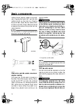
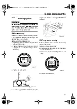
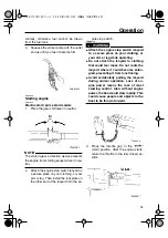
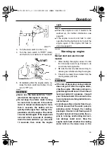
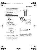
4.

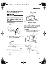
Turn the main switch to “

” (start),

and hold it for a maximum of 5 seconds.

5.

Immediately after the engine starts, re-
lease the main switch and allow it to re-
turn to “

” (on).

CAUTION:


ECM00191 


Never turn the main switch to “

(start) while the engine is running.


Do not keep the starter motor turning
for more than 5 seconds. If the starter
motor is turned continuously for more
than 5 seconds, the battery will be
quickly discharged, thus making it im-
possible to start the engine. The starter
can also be damaged. If the engine will
not start after 5 seconds of cranking,
return the main switch to “

” (on), wait

10 seconds, then crank the engine


again.

NOTE:


When the engine is cold, it needs to be
warmed up. For further information, see
page 30.


If the engine is warm and fails to start,
open the throttle slightly and try to start the
engine again. If the engine still fails to


start, see page 63.


EMU27662


Electric start and remote control models


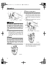
1.

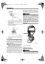
Place the remote control lever in neutral.

NOTE:


The start-in-gear protection device prevents
the engine from starting except when in neu-


tral.

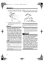
2.

Attach the engine stop switch lanyard to
a secure place on your clothing, or your
arm or leg. Then install the lock plate on
the other end of the lanyard into the en-
gine stop switch.

WARNING


EWM00120 


Attach the engine stop switch lanyard
to a secure place on your clothing, or
your arm or leg while operating.


Do not attach the lanyard to clothing
that could tear loose. Do not route the
lanyard where it could become entan-
gled, preventing it from functioning.


Avoid accidentally pulling the lanyard
during normal operation. Loss of en-
gine power means the loss of most
steering control. Also, without engine
power, the boat could slow rapidly. This
could cause people and objects in the


boat to be thrown forward.

Summary of Contents for F100B

Page 1: ...OWNER S MANUAL F80A F100A F100B 67F 28199 79 E0 ...

Page 2: ...EMU25050 Read this owner s manual carefully before operating your outboard motor ...

Page 3: ...r machine and this manual If there is any question concerning this manu al please consult your Yamaha dealer To ensure long product life Yamaha recom mends that you use the product and perform the specified periodic inspections and main tenance by correctly following the instruc tions in the owner s manual Note that if you do not follow these instructions not only may the product break down but th...

Page 4: ...h on bottom engine cowling 15 Trim tab with anode 15 Tilt support lever for power trim and tilt or hydro tilt model 16 Top cowling lock lever pull up type 16 Flushing device 17 Warning indicator 17 Digital tachometer 17 Low oil pressure warning indicator 18 Overheat warning indicator digital type 18 Speedometer digital type 18 Trim meter digital type 19 Hour meter 19 Hour meter digital type 19 Tri...

Page 5: ...tem 50 Inspecting fuel filter 51 Cleaning fuel filter 51 Inspecting idling speed 52 Changing engine oil 52 Checking wiring and connectors 54 Exhaust leakage 54 Water leakage 54 Engine oil leakage 54 Checking power trim and tilt system 54 Checking power trim and tilt power tilt system 55 Checking propeller 56 Removing the propeller 57 Installing the Propeller 57 Changing gear oil 58 Cleaning fuel t...

Page 6: ... in case your outboard motor is sto len EMU25190 Key number If a main key switch is equipped with the mo tor the key identification number is stamped on your key as shown in the illustration Record this number in the space provided for reference in case you need a new key EMU25202 EC label Engines affixed with this label conform to certain portions of the European Parliament directive relating to ...

Page 7: ...orm to SAV the Swiss exhaust emission regulations for Swiss inshore waters Approval label of emission control certif icate Fuel requirement label 1 EC label location 1 ZMU04215 ZMU01696 1 Approval label location 1 Fuel requirement label location 1 ZMU05067 YAMAHA MOTOR CO LTD Motorfamilie Abgastypenpruf Nummer ZMU04492 1 ZMU05068 ...

Page 8: ...ryone should wear PFDs when there are potentially hazardous boating condi tions Gasoline is highly flammable and its va pors are flammable and explosive Handle and store gasoline carefully Make sure there are no gas fumes or leaking fuel be fore starting the engine This product emits exhaust gases which contain carbon monoxide a colorless odorless gas which may cause brain dam age or death when in...

Page 9: ...h or remove electrical parts when starting or during operation Keep hands hair and clothes away from flywheel and other rotating parts while engine is running EMU25540 Fueling instructions WARNING EWM00010 GASOLINE AND ITS VAPORS ARE HIGH LY FLAMMABLE AND EXPLOSIVE Do not smoke when refueling and keep away from sparks flames or other sources of ignition Stop engine before refueling Refuel in a wel...

Page 10: ...ECM01060 Do not use a battery that does not meet the specified capacity If a battery which does not meet specifications is used the electric system could perform poorly or be overloaded causing electric system damage For electric start models choose a battery Recommended gasoline Regular unleaded gasoline with a min imum octane rating of 90 Research Octane Number Recommended engine oil 4 stroke mo...

Page 11: ...opeller with a different pitch would be more appropriate For a greater operating load a smaller pitch propeller is more suit able as it enables the correct engine speed to be maintained Conversely a larger pitch propeller is more suitable for a smaller oper ating load Yamaha dealers stock a range of propellers and can advise you and install a propeller on your outboard that is best suited to your ...

Page 12: ...the proper operating range For instructions on propeller removal and in stallation see page 56 EMU25760 Start in gear protection Yamaha outboard motors affixed with the pictured label or Yamaha approved remote control units are equipped with start in gear protection device s This feature permits the engine to be started only when it is in neutral Always select neutral before starting the en gine 1...

Page 13: ...8 7 1 2 3 4 5 6 12 2 13 14 15 16 ZMU05070 1 Top cowling 2 Top cowling lock lever 3 Drain screw 4 Anti cavitation plate 5 Trim tab anode 6 Propeller 7 Cooling water inlet 8 Anode 9 Clamp bracket 10 Tilt support lever 11 Flushing device 12 Power trim and tilt switch 13 Remote control box side mount type 14 Fuel tank 15 Digital tachometer 16 Digital speedometer ...

Page 14: ...nform to relevant licensing or approval authority regula tions TRIP TIME BATT Km h knot mph km mile SPEED YAMAHA set mode 10 9 8 7 3 4 5 6 2 1 12 13 15 16 14 2 11 ZMU05071 1 Top cowling 2 Top cowling lock lever 3 Drain screw 4 Anti cavitation plate 5 Trim tab anode 6 Propeller 7 Cooling water inlet 8 Anode 9 Clamp bracket 10 Tilt support lever 11 Flushing device 12 Power trim and tilt switch 13 Re...

Page 15: ...the shifter and the throttle The electrical switch es are mounted on the remote control box EMU26190 Remote control lever Moving the lever forward from the neutral po sition engages forward gear Pulling the le ver back from neutral engages reverse The engine will continue to run at idle until the le ver is moved about 35 a detent can be felt Moving the lever farther opens the throttle and the engi...

Page 16: ...control lever is in neutral The remote control lever will operate only when the neutral throttle lever is in the closed position EMU25911 Tiller handle To change direction move the tiller handle to the left or right as necessary EMU25922 Gear shift lever Pulling the gear shift lever towards you puts the engine in forward gear so that the boat moves ahead Pushing the lever away from you puts the en...

Page 17: ...d fuel economy for the desired operation EMU25970 Throttle friction adjuster A friction device provides adjustable resis tance to movement of the throttle grip or the remote control lever and can be set accord ing to operator preference To increase resistance turn the adjuster clockwise To decrease resistance turn the adjuster counterclockwise WARNING EWM00030 Do not overtighten the friction adjus...

Page 18: ...WM00120 Attach the engine stop switch lanyard to a secure place on your clothing or your arm or leg while operating Do not attach the lanyard to clothing that could tear loose Do not route the lanyard where it could become entan gled preventing it from functioning Avoid accidentally pulling the lanyard during normal operation Loss of en gine power means the loss of most steering control Also witho...

Page 19: ... returns automatically to the on position EMU26110 Steering friction adjuster A friction device provides adjustable resis tance to the steering mechanism and can be set according to operator preference An ad juster lever is located on the bottom of the tiller handle bracket To increase resistance turn the lever to the left To decrease resistance turn the lever to the right WARNING EWM00040 Do not ...

Page 20: ... motor will stop in its current position WARNING EWM01030 Use the power trim and tilt switch located on the bottom engine cowling only when the boat is at a complete stop with the en gine off Attempting to use this switch while the boat is moving could increase the risk of falling overboard and could distract the operator increasing the risk of collision with another boat or an obsta cle NOTE For ...

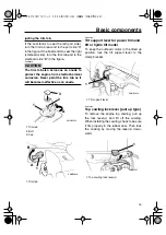
Page 21: ...come ineffective as an anode EMU26340 Tilt support lever for power trim and tilt or hydro tilt model To keep the outboard motor in the tilted up position lock the tilt support lever to the clamp bracket EMU26382 Top cowling lock lever pull up type To remove the engine top cowling pull up the lock lever s and lift off the cowling When installing the cowling check to be sure it fits properly in the ...

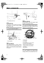
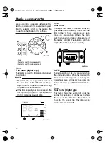
Page 22: ...ter The tachometer shows the engine speed and has the following functions NOTE All segments of the display will light momen tarily after the main switch is turned on and will return to normal thereafter NOTE The water separator and engine trouble warning indicators only operate when the en 1 Top cowling lock lever s 1 Flushing device ZMU04226 1 1 ZMU04256 1 Tachometer 2 Trim meter 3 Hour meter 4 L...

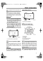
Page 23: ...ator digital type If the engine temperature rises too high the warning indicator will start to blink For fur ther information on reading the indicator see page 22 CAUTION ECM00050 Do not continue to run the engine if the overheat warning indicator is on Serious engine damage will occur EMU26600 Speedometer digital type This gauge shows the boat speed NOTE After the main switch is first turned on a...

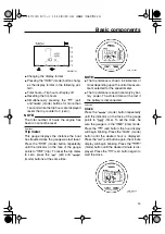
Page 24: ...n the en gine inside the top cowling It measures the total number of hours the engine has been run since manufacture When the main switch is turned on initially all segments of the display will light The indicator will then display the number of hours normally NOTE The number of hours is only measured when the engine is running When the main switch is turned on but the engine is not running the di...

Page 25: ...ts to trip To reset the trip meter to zero press the set and mode buttons at the same time NOTE The trip distance is shown in kilometers or miles depending upon the unit of measure ment selected for the speedometer The trip distance is kept in memory by bat tery power The stored data will be lost if the battery is disconnected EMU26700 Clock Press the mode button repeatedly until the indicator on ...

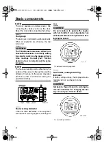
Page 26: ...ion of the sensor in the fuel tank and the attitude of the boat in the water Operation with bow up trim or continuous turning can give false readings EMU26720 Fuel warning indicator If the fuel level decreases to one segment the fuel level warning segment will begin to blink CAUTION ECM00880 Do not continue to operate the engine with full throttle if a warning device has activated Get back to the ...

Page 27: ...ce Engine speed will automatically decrease to about 3000 r min The overheat warning indicator will light if equipped on the bottom cowling or the ta chometer The buzzer will sound If the warning system has activated stop the engine and check the cooling water inlet for clogging EMU26861 Low oil pressure warning If the oil pressure drops too low the warning device will activate Activation of warni...

Page 28: ...e as soon as it is safe to do so Check the oil level and add oil as needed If the oil level is correct consult your Yamaha dealer CAUTION ECM00100 Do not continue to run the engine if the low oil pressure warning indicator is on Serious engine damage could occur ZMU02360 ...

Page 29: ...n is intended as reference only It is not possible to provide complete in structions for every possible boat and motor combination Proper mounting depends in part on experience and the specific boat and motor combination WARNING EWM00830 Improper mounting of the outboard mo tor could result in hazardous conditions such as poor handling loss of control or fire hazards Observe the following For perm...

Page 30: ...g parts to wear in evenly Correct break in will help en sure proper performance and longer engine life CAUTION ECM00800 Failure to follow the break in procedure could result in reduced engine life or even severe engine damage EMU27080 Procedure for 4 stroke models Run the engine under load in gear with a propeller installed as follows 1 For the first hour of operation Run the engine at 2000 r min ...

Page 31: ...engine and engine mounting Look for loose or damaged fasteners Check the propeller for damage EMU27163 Checking the engine oil level 1 Put the outboard motor in an upright po sition not tilted 2 Remove oil dipstick and wipe it clean 3 Completely insert the dipstick and re move it again 4 Check the oil level using the dipstick to be sure the level falls between the upper and lower marks Fill with o...

Page 32: ...ain from smoking and keep away from open flames and sparks while loosen ing the air vent screw This product emits exhaust gases which contain carbon monoxide a col orless odorless gas which could cause brain damage or death when inhaled Symptoms include nausea dizziness and drowsiness Keep cockpit and cab in areas well ventilated Avoid blocking exhaust outlets 1 If there is an air vent screw on th...

Page 33: ... of the lanyard into the en gine stop switch WARNING EWM00120 Attach the engine stop switch lanyard to a secure place on your clothing or your arm or leg while operating Do not attach the lanyard to clothing that could tear loose Do not route the lanyard where it could become entan gled preventing it from functioning Avoid accidentally pulling the lanyard during normal operation Loss of en gine po...

Page 34: ...slightly and try to start the engine again If the engine still fails to start see page 63 EMU27662 Electric start and remote control models 1 Place the remote control lever in neutral NOTE The start in gear protection device prevents the engine from starting except when in neu tral 2 Attach the engine stop switch lanyard to a secure place on your clothing or your arm or leg Then install the lock p...

Page 35: ...he engine again If the engine still fails to start see page 63 EMU27670 Warming up engine EMU27710 Manual start and electric start models 1 After starting the engine allow it to idle for 3 minutes to warm up Failure to do so will shorten engine life 2 Be sure the low oil pressure warning in dicator goes off after starting the engine 3 Check for a steady flow of water from the cooling water pilot h...

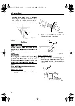
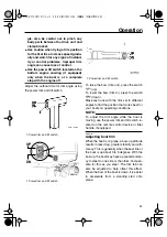
Page 36: ...shifting position from forward to reverse or vice versa first close the throttle so that the engine idles or runs at low speeds EMU27763 Forward tiller handle and remote control models Tiller control models 1 Place the throttle grip in the fully closed position 2 Move the gear shift lever quickly and firmly from neutral to forward Remote control models 1 Pull up the neutral interlock trigger if eq...

Page 37: ... fully closed position 2 Move the gear shift lever quickly and firmly from neutral to reverse Remote control models 1 Pull up the neutral interlock trigger if equipped and move the remote control lever quickly and firmly from neutral to reverse EMU27820 Stopping engine Before stopping the engine first let it cool off for a few minutes at idle or low speed Stop ping the engine immediately after ope...

Page 38: ...e performance and fuel economy while reducing strain on the engine Correct trim angle depends upon the combination of boat engine and propeller Correct trim is also affected by variables such as the load in the boat sea conditions and running speed WARNING EWM00740 Excessive trim for the operating condi tions either trim up or trim down can cause boat instability and can make steering the boat mor...

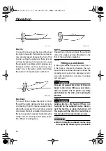
Page 39: ...different angles to find the position that works best for your boat and operating conditions NOTE To adjust the trim angle while the boat is moving use the power trim and tilt switch lo cated on the remote control device or tiller handle if equipped EMU27911 Adjusting boat trim When the boat is on plane a bow up attitude results in less drag greater stability and effi ciency This is generally when...

Page 40: ...difficult and dangerous NOTE Depending on the type of boat the outboard motor trim angle may have little effect on the trim of the boat when operating EMU27933 Tilting up and down If the engine will be stopped for some time or if the boat is moored in shallows the out board motor should be tilted up to protect the propeller and casing from damage by colli sion with obstructions and also to reduce ...

Page 41: ...or tilting up Power trim and tilt models power tilt models 1 Place the remote control lever the gear shift lever in neutral 2 Disconnect the fuel line from the out board motor or close the fuel cock 3 Press the power trim and tilt switch power tilt switch up until the out board motor has tilted up completely 4 Push the tilt support knob into the clamp bracket or pull the tilt support lever to ward...

Page 42: ...0250 Be sure to retract the trim rods complete ly during mooring This protects the rods from marine growth and corrosion which could damage the power trim and tilt mechanism EMU28053 Procedure for tilting down Power trim and tilt models power tilt models 1 Push the power tilt power trim and tilt switch up until the outboard motor is supported by the tilt rod and the tilt support lever tilt support...

Page 43: ...hallow water cruising Return the outboard motor to its normal position as soon as the boat is back in deeper water CAUTION ECM00260 Do not tilt the outboard motor up so that the cooling water inlet on the lower unit is above the surface of the water when set ting up for and cruising in shallow water Otherwise severe damage from overheat ing can result EMU28184 Procedure for power trim and tilt pow...

Page 44: ...ng in salt water After operating in salt water wash out the cooling water passages with fresh water to prevent them from becoming clogged with salt deposits NOTE For cooling system flushing instructions see page 41 Cruising in turbid water Yamaha strongly recommends that you use the optional chromium plated water pump kit not available for some models if you use the outboard motor in turbid muddy ...

Page 45: ...lb F80AET 174 0 kg 384 lb Weight SUS X F100AET 178 0 kg 392 lb F100BET 189 5 kg 418 lb F80AET 178 0 kg 392 lb Performance Full throttle operating range 5000 6000 r min Maximum output F100AET 73 6 kW 5500 r min 100 HP 5500 r min F100BET 73 6 kW 5500 r min 100 HP 5500 r min F80AET 58 8 kW 5500 r min 80 HP 5500 r min Idling speed in neutral 850 50 r min Engine Type 4 stroke L Displacement 1596 0 cm3 ...

Page 46: ...opeller nut F100AET 35 0 Nm 25 8 ft lb 3 57 kgf m F100BET 55 0 Nm 40 6 ft lb 5 61 kgf m F80AET 35 0 Nm 25 8 ft lb 3 57 kgf m Engine oil drain bolt 28 0 Nm 20 7 ft lb 2 86 kgf m Engine oil filter 18 0 Nm 13 3 ft lb 1 84 kgf m EMU28222 Transporting and storing outboard motor WARNING EWM00690 Leaking fuel is a fire hazard When transporting and storing the outboard motor close the air vent screw and f...

Page 47: ...ring or transporting the outboard motor on its side not up right put it on a cushion after draining the engine oil Do not place the outboard motor on its side before the cooling water has drained from it completely otherwise water may enter the cylinder through the exhaust port and cause engine trou ble Store the outboard motor in a dry well ventilated place not in direct sunlight EMU28301 Procedu...

Page 48: ...comes empty and the engine stops 11 Drain the cooling water completely out of the motor Clean the body thoroughly 12 If the Fogging Oil is not available re move the spark plug s Pour a tea spoonful of clean engine oil into each cylinder Crank several times manually Replace the spark plug s NOTE A flushing attachment is available from your Yamaha dealer EMU28400 Lubrication except oil injection mod...

Page 49: ...isconnect and remove the battery from the boat Always disconnect the black negative cable first to prevent the risk of shorting 2 Clean the battery casing and terminals Fill each cell to the upper level with dis tilled water 3 Store the battery on a level surface in a cool dry well ventilated place out of di rect sunlight 4 Once a month check the specific gravity of the electrolyte and recharge as...

Page 50: ...e exterior of the outboard motor with fresh water Flush the cooling system with fresh water NOTE For cooling system flushing instructions see page 41 EMU28460 Checking painted surface of motor Check the motor for scratches nicks or flak ing paint Areas with damaged paint are more likely to corrode If necessary clean and paint the areas A touch up paint is avail able from your Yamaha dealer EMU2847...

Page 51: ...y water the engine should be flushed with clean water after each use The symbol indicates the check ups which you may carry out yourself The symbol indicates work to be carried out by your Yamaha dealer Item Actions Initial Every 10 hours 1 month 50 hours 3 months 100 hours 6 months 200 hours 1 year Anode s external Inspection replace ment Anode s internal Inspection replace ment Battery Inspectio...

Page 52: ... throttle pick up timing Inspection adjustment Water pump Inspection replace ment Engine oil Inspection change Oil filter cartridge Change Spark plug s Cleaning adjustment replacement Timing belt Inspection replace ment Item Actions Every 500 hours 2 5 years 1000 hours 5 years Timing belt Replacement Valve clearance DOHC Inspection adjustment Exhaust guide exhaust manifold Inspection replace ment ...

Page 53: ...Maintenance 48 EMU28940 Greasing Yamaha grease A water resistant grease Yamaha grease D corrosion resistant grease for propeller shaft F80A F100A ZMU04237 ...

Page 54: ...ug can indicate something about the condition of the engine For exam ple if the center electrode porcelain is very white this could indicate an intake air leak or carburetion problem in that cylinder Do not attempt to diagnose any problems yourself Instead take the outboard motor to a Yamaha dealer You should periodically re move and inspect the spark plug because heat and deposits will cause the ...

Page 55: ...n as possible with a torque wrench EMU28962 Checking fuel system WARNING EWM00060 Gasoline and its vapors are highly flam mable and explosive Keep away from sparks cigarettes flames or other sources of ignition WARNING EWM00910 Leaking fuel can result in fire or explo sion Check for fuel leakage regularly If any fuel leakage is found the fuel system must be repaired by a qualified mechanic Imprope...

Page 56: ...filter cup and hoses in place Improper assembly or replacement could result in a fuel leak which could result in a fire or explosion hazard EMU29021 Cleaning fuel filter NOTE If any water is in the fuel the float will rise If so remove the cup and drain the water 1 Remove the nut holding the fuel filter as sembly if so equipped 2 Unscrew the filter cup catching any spilled fuel in a rag 3 Remove t...

Page 57: ...idle speed will measure higher than normal If you have difficulty ver ifying the idle speed or the idle speed re quires adjustment consult a Yamaha dealer or other qualified mechanic 2 Verify whether the idle speed is set to specification For idle speed specifica tions see page 40 EMU29073 Changing engine oil WARNING EWM00760 Avoid draining the engine oil immedi ately after stopping the engine The...

Page 58: ...f oil through the filler hole Install the filler cap 5 Start the engine and watch to make sure the low oil pressure warning indicator if equipped turns off Make sure that there are no oil leaks CAUTION ECM00680 If the low oil pressure warning indicator does not turn off or if there are oil leaks stop the engine and find the cause Con tinued operation with a problem could cause severe engine damage...

Page 59: ...linder EMU29130 Water leakage Start the engine and check that no water leaks from the joints between the exhaust cover cylinder head and body cylinder EMU29140 Engine oil leakage Check for oil leaks on the around the engine NOTE If any leaks are found consult your Yamaha dealer EMU29153 Checking power trim and tilt system WARNING EWM00430 Never get under the lower unit while it is tilted even when...

Page 60: ...nto the cylinders 7 Activate the trim up switch until the tilt rod is fully extended Unlock the tilt sup port lever 8 Tilt the outboard motor down Check that the tilt rod and trim rods operate smoothly NOTE Consult your Yamaha dealer if any operation is abnormal EMU29162 Checking power trim and tilt power tilt system WARNING EWM00430 Never get under the lower unit while it is tilted even when the ...

Page 61: ...sly injured if the en gine accidentally starts when you are near the propeller Before inspecting removing or install ing the propeller remove the spark plug caps from the spark plugs Also place the shift control in neutral turn the main switch to off and re move the key and remove the lanyard from the engine stop switch Turn off the battery cut off switch if your boat has one Do not use your hand ...

Page 62: ...Spline models CAUTION ECM00340 Be sure to install the thrust washer be fore installing the propeller otherwise the lower case and propeller boss could be damaged Be sure to use a new cotter pin and bend the ends over securely Otherwise the propeller could come off during op eration and be lost 1 Apply Yamaha marine grease or a cor rosion resistant grease to the propeller shaft 2 Install the spacer...

Page 63: ...gnetic gear oil drain screw equipped remove all metal particles from the screw before installing it 4 Remove the oil level plug to allow the oil to drain completely CAUTION ECM00710 Inspect the used oil after it has been drained If the oil is milky water is getting into the gear case which can cause gear damage Consult a Yamaha dealer for re pair of the lower unit seals NOTE For disposal of used o...

Page 64: ...l tank carefully Im proper assembly can result in a fuel leak which could result in a fire or ex plosion hazard Dispose of old gasoline according to lo cal regulations 1 Empty the fuel tank into an approved container 2 Pour a small amount of suitable solvent into the tank Install the cap and shake the tank Drain the solvent completely 3 Remove the screws holding the fuel joint assembly Pull the as...

Page 65: ...ric acid and therefore is poisonous and highly caustic Always follow these preventive mea sures Avoid bodily contact with electrolytic fluid as it can cause severe burns or permanent eye injury Wear protective eye gear when han dling or working near batteries Antidote EXTERNAL SKIN Flush with water EYES Flush with water for 15 minutes and get immediate medical attention Antidote INTERNAL Drink lar...

Page 66: ...3 If the battery will be stored for longer than a month check the specific gravity of the fluid at least once a month and re charge the battery when it is low NOTE Consult a Yamaha dealer when charging or re charging batteries EMU29331 Connecting the battery WARNING EWM00570 Mount the battery holder securely in a dry well ventilated vibration free loca tion in the boat Install a fully charged bat ...

Page 67: ...t is loose have it re paired by your Yamaha dealer EMU29400 Coating the boat bottom A clean hull improves boat performance The boat bottom should be kept as clean of ma rine growth as possible If necessary the boat bottom can be coated with an anti foul ing paint approved for your area to inhibit marine growth Do not use anti fouling paint which includes copper or graphite These paints can cause m...

Page 68: ...A Have serviced by a Yamaha dealer Q Is shift lever in gear A Shift to neutral Engine will not start starter operates Q Is fuel tank empty A Fill tank with clean fresh fuel Q Is fuel contaminated or stale A Fill tank with clean fresh fuel Q Is fuel filter clogged A Clean or replace filter Q Is starting procedure incorrect A See page 28 Q Has fuel pump malfunctioned A Have serviced by a Yamaha deal...

Page 69: ...p damaged A Have serviced by a Yamaha dealer Q Is air vent screw on fuel tank closed A Open air vent screw Q Is choke knob pulled out A Return to home position Q Is motor angle too high A Return to normal operating position Q Is carburetor clogged A Have serviced by a Yamaha dealer Q Is fuel joint connection incorrect A Connect correctly Q Is throttle valve adjustment incorrect A Have serviced by ...

Page 70: ...ed or of incorrect type A Inspect spark plug s Clean or replace with recommended type Q Are weeds or other foreign matter tangled on gear housing A Remove foreign matter and clean lower unit Q Is fuel system obstructed A Check for pinched or kinked fuel line or other obstructions in fuel system Q Is fuel filter clogged A Clean or replace filter Q Is fuel contaminated or stale A Fill tank with clea...

Page 71: ...damage WARNING EWM00870 The outboard motor can be seriously damaged by a collision while operating or trailering Damage could make the out board motor unsafe to operate If the outboard motor hits an object in the wa ter follow the procedure below 1 Stop the engine immediately 2 Inspect the control system and all com ponents for damage Also inspect the boat for damage 3 Whether damage is found or n...

Page 72: ...ter mechanism does not operate the engine cannot be cranked with the start er the engine can be started with an emer gency starter rope WARNING EWM01020 Use this procedure only in an emergen cy and only to return to port for repairs When the emergency starter rope is used to start the engine the start in gear protection device does not oper ate Make sure the remote control lever is in neutral Othe...

Page 73: ...her objects away when starting the engine Use the emergency starter rope only as instructed Do not touch the fly wheel or other moving parts when the engine is running Do not install the starter mechanism or top cowling after the engine is running Do not touch the ignition coil spark plug wire spark plug cap or other elec trical components when starting or op erating the motor You could get an ele...

Page 74: ...stem malfunction If the battery voltage is low or in the unlikely event of an ignition system malfunction the engine speed may become erratic or the en gine may stop In such a situation follow the procedure below 1 Remove the CDI unit cover or electrical cover if equipped 2 Disconnect the yellow cord emergency circuit of the CDI unit to return to port WARNING EWM00350 When the yellow cord is disco...

Page 75: ...e the spark plug s then face the spark plug holes downward to allow any water mud or contaminants to drain 3 Drain the fuel from the carburetor fuel filter and fuel line Drain the engine oil completely 4 Fill the sump with the fresh engine oil 5 Feed engine fogging oil or engine oil through the carburetor s and spark plug holes while cranking the engine with the manual starter or emergency starter...

Page 76: ...YAMAHA MOTOR CO LTD Printed on recycled paper Printed in Japan April 2005 0 1 1 ...

Reviews: