background image

Block/Level Diagram

33

EMX5000-20/EMX5000-12—Owner’s Manual

Block/Level Diagram

CH INPUT

[–60~–16dB]

[–34~+10dB]

CH INSER

T

 I/O

[0dB]

EMX5000-12:CH1-8

EMX5000-20:CH1-16

EMX5000-12:CH1-8

EMX5000-20:CH1-16

A

B

GAIN

[–60~–16dB]

[–34~+10dB]

PHANT

OM

8CH/SW

EMX5000-12:[CH1-8]

EMX5000-20:[CH1-8] [CH9-16]

PA

D

HPF

HPF

BA

HA

+48V

26dB

[0dB]

[0dB]

[0dB]

3-Stage EQ

Lo Gain

Hi Gain

Mid f

Mid Gain

BA

ON

[–10dB]

[0dB]

CH Fader

PEAK

SIGNAL

PA

N

POST

PFL

POST

EFFECT1

EFFECT2

AUX1

AUX2

[0dB]

[–6dB]

[–6dB]

[–6dB]

[–6dB]

STEREO L (NON-MUTE)

STEREO R (NON-MUTE)

EFFECT1 (NON-MUTE)

EFFECT2 (NON-MUTE)

AUX1 (NON-MUTE)

AUX2 (NON-MUTE)

STEREO L (MUTE)

STEREO R (MUTE)

EFFECT1 (MUTE)

EFFECT2 (MUTE)

AUX1 (MUTE)

AUX2 (MUTE)

PFL L

 / AFL

 L

PFL R / 

AFL R

PFL

AFL

SUM

SUM

SUM

SUM

[0dB]

[0dB]

[0dB]

[0dB]

ST

AND-BY

EMX5000-12:CH1-8

EMX5000-20:CH1-16

SUM

SUM

[0dB]

[0dB]

REC OUT

[–10dBV]

L

R

9-Stage GEQ

9-Stage GEQ

63Hz

125Hz

250Hz

500Hz

1kHz

2kHz

4kHz

8kHz

16kHz

GEQ

BA

BA

BA

BA

[–6dB]

[–10dB]

ST

 OUT

ST

 SUB OUT

DR

DR

ST

 SUB OUT

[+4dB]

L

R

ST

 OUT

[+4dB]

L

R

PEAK

PEAK

YSP

YSP

POWER AMP

 IN

[+4dB]

Y

AMAHA

SPEAKER

PROCESSING

A

B

PA

LIMITTER

LIMITTER

PROTECT

OR

Power Select

PA

SPEAKERS

[500Wmax@4ohms]

A

A

BRIDGE

B

2

1

1

2

500W

300W

100W

500W

300W

100W

+1

–1

+2

–2

+1

–1

+2

–2

POWER AMP

 Controls

INV

Signal Select

MAIN L

AUX1

AUX1

MONO BRIDGE

MAIN R

MONO

AUX2

MONO BRIDGE

FREQ

80–120Hz (12dB/oct)

INV

LPF

LPF

SUM

MONO OUT [+4dB]

[–10dB]

MONO OUT

BA

BA

AUX SEND1

[+4dB]

AUX SEND2

[+4dB]

[–10dB]

AUX1

[–10dB]

AUX2

AFL

AFL

AFL

SUM

SUM

SUM

[0dB]

SUM

[0dB]

SUM

[0dB]

[0dB]

[0dB]

SUM

[0dB]

SUM

SUM

SUM

[–6dB]

SUM

[–6dB]

SUM

[0dB]

SUM

[0dB]

INV

[0dB]

INV

[0dB]

PFL

POST

POST

BAL

EFFECT1

EFFECT2

AUX1

AUX2

[0dB]

[–6dB]

[–6dB]

[–6dB]

[–6dB]

DN

BA

BA

[0dB]

[0dB]

[–10dB]

ST

 CH Fader

PEAK

SIGNAL

GAIN

[–34~+10dB]

ST

 CH INPUT

[–34~+10dB]

EMX5000-12:CH9(L)/10(R),CH1

1(L)/12(R)

EMX5000-20:CH17(L)/18(R),CH19(L)/20(R)

HA

HA

[0dB]

L

R

3-Stage EQ

3-Stage EQ

Lo

Hi

Mid

BA

BA

PA

D

PA

D

PFL

AUX1

ST

AUX2

[0dB]

[+4dB]

[–6dB]

[–6dB]

[–6dB]

[–6dB]

[–16dB]

[–16dB]

ST

 SUB IN 1,2

[+4dB]

L

 (MONO)

R

2TR IN

[–10dBV]

BA

BA

[0dB]

[–6dB]

[–6dB]

L

R

PROGRAM

P

ARAMETER

PROGRAM

P

A

RAMETER

DIGIT

A

L

EFFECT1

ON

ON

IN

L

 OUT

R OUT

DIGIT

A

L

EFFECT2

IN

L

 OUT

R OUT

ST

EFFECT1 R

T

N

EFFECT2 R

T

N

PFL

PFL

PFL

AUX1

AUX2

[–12dB]

[–12dB]

AUX1

AUX2

[–12dB]

[–12dB]

FOOT

 SWITCH

TA

P

TA

P

ON/OFF

0dB=0.775V

0dBV=1V

+30dB

+20dB

+10dB

0dB

–10dB

–20dB

–30dB

–40dB

–50dB

–60dB

ST

 CH INPUT

GAIN Min. [+10dB]

ST

 CH INPUT

GAIN Max. [–34dB]

CH INPUT

 A, B

GAIN Max. [–60dB]

CH INPUT

 A, B GAIN Min. [–16dB]

ST

 SUB IN [+4dB]

CH & ST

 CH to ST

 [0dB] (P

AN, BAL

 turned hard left/right)

CH & ST

 CH to 

AUX/EFFECT

 [–6dB]

ST

 SUB IN to ST/AUX  [–6dB]

2TR IN to ST

 [–6dB]

2TR IN [–10dBV]

fader [–10dB]

[PHONES 3mW@40ohms]

ST

 OUT•ST

 SUB OUT•MONO OUT

 [+4dB]

AUX SEND, EFFECT

 SEND [+4dB]

REC OUT

 [–10dBV]

PHONES [–16dB]

ST

 SUB level control [–6dB]

EFFECT

 [–6dB]

ST•MONO•AUX fader [–10dB]

SPEAKERS OUT

MAXIMUM OUTPUT

 POWER 500W/4

100W/4

+40dB

+30dB

+20dB

+10dB

0dB

–10dB

–20dB

–30dB

–40dB

–50dB

–60dB

INV

INV

INV

INV

EFFECT

 SEND1

[+4dB]

EFFECT

 SEND2

[+4dB]

PHONES

[3mW@40ohms]

[–16dB]

PHONES

Summary of Contents for EMX 5000-12

Page 1: ...Owner s Manual E Keep This Manual For Future Reference ...

Page 2: ...priate impedance of the speakers that can be con nected P 33 Block Level Diagram Power Amplifier output section level diagram bottom right These plots show the nominal output and maximum output levels of signals received at the SPEAKERS jacks If the output level is 4dB Level Meter 0 the internal power amplifier will deliver 100W into a 4Ω load If the output level is 11dB LIMITER indicator lights t...

Page 3: ...OUT BA BA AUX SEND1 4dB AUX SEND2 4dB 10dB AUX1 10dB AUX2 AFL AFL AFL SUM SUM SUM 0dB SUM 0dB SUM 0dB 0dB 0dB SUM 0dB SUM SUM SUM 6dB SUM 6dB SUM 0dB SUM 0dB INV 0dB INV 0dB PFL POST POST BAL EFFECT1 EFFECT2 AUX1 AUX2 0dB 6dB 6dB 6dB 6dB DN BA BA 0dB 0dB 10dB ST CH Fader PEAK SIGNAL GAIN 34 10dB ST CH INPUT 34 10dB EMX5000 12 CH9 L 10 R CH11 L 12 R EMX5000 20 CH17 L 18 R CH19 L 20 R HA HA 0dB L R ...

Page 4: ...ntact Yamaha Corporation of America Electronic Service Division 6600 Orangethorpe Ave Buena Park CA 90620 The above statements apply ONLY to those products distributed by Yamaha Corporation of America or its subsidiaries Explanation of Graphical Symbols The lightning flash with arrowhead symbol within an equilateral triangle is intended to alert the user to the presence of uninsulated dangerous vo...

Page 5: ...eeding this instruction fire or electrical shock may result If you notice any abnormality such as smoke odor or noise or if a foreign object or liquid gets inside the unit turn it off immediately Remove the power cord from the AC outlet Con sult your dealer for repair Using the unit in this condition is a fire and electrical shock hazard CAUTION Keep this unit away from the following locations Loc...

Page 6: ...acing defective components Using a cell phone mobile telephone near this unit may induce noise If noise occurs use the telephone away from the unit Do not set all equalizer controls and faders to maximum Doing so may cause oscillation depending on the condition of the connected unit and speakers and may damage the speakers The digital circuits of this unit may induce a slight noise into nearby rad...

Page 7: ...switch lets you switch the maximum output of the amp between three levels This lets you adjust the maximum output of the inter nal power amp as appropriate for the size of the room or the input capacity of the speakers Two multi effect units are built in each providing six teen types of effect equivalent in quality to the acclaimed Yamaha SPX series of multi effect units The effects can be used to...

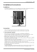
Page 8: ...with a Speakon connector can also be con nected using a Speakon cable In this case use the SPEAKERS 1 jacks to output the signal from the EMX5000 20 EMX5000 12 When connecting a Speakon connector to the EMX5000 20 EMX5000 12 be sure to turn the plug to the right to lock the connection after inserting the plug Never connect the speakers in the manner shown below Otherwise the EMX5000 20 EMX5000 12 ...

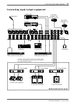
Page 9: ...turned on Connecting a CD player MD player and or cassette deck Connect a CD player or MD player to the 2TR IN jacks Refer to the operation manual of the corre sponding device for more information on the input and output of the device To connect a second player use the LINE jack Connect a recorder to the REC OUT jacks Connecting an electric acoustic guitar or electric bass Connect electric acousti...

Page 10: ...specified above to prevent the speakers from being damaged To correct the low range turn on the YAMAHA SPEAKER PROCESSING switch in the upper right corner of the panel Sound output Set the ST OUT fader and the input channel fad ers to the position and while playing the instrument or singing into the mic connected to the channel you want to check raise the GAIN control of the channel so that the PE...

Page 11: ... the effect depth by turning the EFF1 control of the channel to which you want to apply the effect Power off 1 Press the POWER switch of the EMX5000 20 EMX5000 12 to turn off the power to the unit 2 Turn off the power to all connected devices Be sure to follow the power off sequence specified above to prevent the speakers from being dam aged In preparation for the next time you will use the EMX500...

Page 12: ...uency region below 80 Hz will be attenuated at 18 dB octave 4 Equalizer controls HIGH MID LOW This is a 3 band equalizer that adjusts the high frequency range mid frequency range and low frequency range of each channel When the HIGH and LOW knobs are in the position the high and low ranges will have a flat response Turning a knob toward the right will boost the corresponding frequency range and tu...

Page 13: ...O bus 9 ON switch indicator This is an on off switch for the input signal of each channel The indicator will light if this switch is turned on 0 PEAK indicator The indicator will light 3 dB before clipping warning that clipping level is near A SIGNAL indicator This indicator will light if a signal is being input to the corresponding channel B PFL pre fader listen switch Channels for which this swi...

Page 14: ...SPEAKERS B 1 2 jacks to the speakers If the Power amp select switch Y is set to MONO BRIDGE this fader adjusts the level of the signal sent from the SPEAKERS A 1 jacks to the speaker K ST OUT fader The ST OUT fader adjusts the final level of the signal sent from the STEREO bus to the ST OUT jacks input output panel 0 If the Power amp select switch Y is set to ST L R this fader also adjusts the lev...

Page 15: ...e internal effect type you can press this switch to set the desired delay time Press the TAP switch several times and the inter val between the last two presses will be set as the delay time The specified time will be remem bered even if the power is turned off The LED beside the switch will blink in synchro nization with the delay time only when the effect type is TAP DELAY S EFFECT 1 2 ON switch...

Page 16: ...the rear panel ST L R The STEREO bus signals are output from the SPEAKERS A 1 2 jacks and the SPEAKERS B 1 2 jacks The final level of these signals is adjusted by the master ST OUT fader AUX 1 MONO The AUX 1 bus signals are output from the SPEAKERS A 1 2 jacks and a monaural signal that is a mix of the STEREO bus signals is output from the SPEAKERS B 1 2 jacks The final level of these signals is a...

Page 17: ...m the ST OUT jacks The 0 indicator lights up when the output level reaches 4 dB a PHONES control This knob adjusts the level of the signal moni tored via the PHONES jack input output panel D b ST SUB OUT control This knob adjusts the final level of the signal sent from the STEREO bus to the ST SUB OUT jacks input output panel A c LPF control ON OFF switch This switch applies a low pass filter to t...

Page 18: ...ct processor such as a com pressor limiter between the equalizer and fader of input channels These connections require a special Y cable such as shown in the following diagram The nominal input output levels are 0 dB A 5 6 8 E F G 0 D 1 4 3 2 7 B C 9 INPUT A jacks XLR type INPUT B jacks TRS phone jacks Pin 1 ground Sleeve ground Pin 2 hot Tip hot Pin 3 cold RIng cold GND R S T GND 1 2 3 Note It is...

Page 19: ...ect unit such as a delay or echo can be connected to this jack The signal adjusted by the EFF 1 2 control of each channel will be sent to the EFFECT 1 2 bus and output from this jack The nominal output level is 4 dB 0 ST OUT jacks These phone jacks output the line level signal of the STEREO bus The final output level from these jacks is adjusted by the ST OUT fader con trol panel K The nominal out...

Page 20: ...ect the socket end of the included AC cable to this inlet Connect the plug end of the cable to an AC outlet of the voltage printed below the inlet 2 POWER switch This switch turns on off the power to the EMX5000 20 EMX5000 12 3 SPEAKERS speaker output jacks These jacks are used to connect speakers Jacks 1 are Speakon type connectors Jacks 2 are 1 4 phone jacks The setting of the control panel powe...

Page 21: ...elect switch is set to ST L R AUX 1 MONO or AUX 1 AUX 2 Select either one or two speakers each to jacks A and jacks B Make connections to either jacks 1 or 2 depend ing on the type of speaker cable you are using When the power amp select switch is in the ST L R position the signals of the stereo L and R bus will be out put from the speakers connected to jacks A and B respectively When this switch ...

Page 22: ...combined monaural signal of the STEREO bus A maximum output of 1000 W will be obtained when an 8 ohm speaker is used If you are inputting a signal from the P AMP IN jack input it to P AMP IN jack A Caution When using a bridge connection do not connect a speaker to the B or A 2 jack Two channel connection Two channel parallel connection Main Speaker Main Monitor Speaker Main Speaker Main Monitor Sp...

Page 23: ...phone CD player Headphones Effect processor compressor Synthesizer Effect processor reverb Drum machine Power amplifier Power amplifier Power amplifier Additional alternative PA system Normally connect speakers to the jacks on the rear panel If more speaker outputs are needed use the ST SUB OUT jacks and the MONO OUT jack To add main speakers To add monitor speakers To add a subwoofer 88 88 ...

Page 24: ...ualizer and the ST fader in the master section to adjust the overall volume and tone Using the digital effect The EMX5000 20 EMX5000 12 has a built in digital effect allowing reverberation or ambiance to be added to vocals or instrumental sounds 1 Connect a mic or instrument to the desired channels and adjust the volume and tone 2 Press the ON switch of the digital effect section 3 Use the PROGRAM...

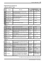
Page 25: ...2 CHORUS Modulates the delay time of the signal to add depth to the sound Depth 0 100 PHASER An effect that changes the phase of the sound to create modulation Modulation frequency 0 05 4 00Hz RADIO VOICE An effect that produces a lo fi sound like that of an AM radio Drive 0 100 TREMOLO An effect that adds modulation to the sound Modulation frequency 0 05 10 00Hz EARLY REF An effect produced by mo...

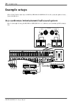
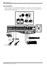
Page 26: ...MX5000 20 EMX5000 12 can be used and explains connec tions and operation As a conference entertainment hall sound system Here is an example of using the EMX5000 20 EMX5000 12 as a conference or entertainment hall sound sys tem Main speakers Microphone Cassette deck for recording CD player Cassette deck for paly back ...

Page 27: ... to the output of the recording cassette deck Connect the main speakers to the SPEAKERS A and B jacks and set the Power amp select switch to ST L R Playing back a CD player 1 Turn on the power to the peripheral devices then to the EMX5000 20 EMX5000 12 2 Start playback on the CD player Use the GAIN control of channel 17 18 EMX5000 20 9 10 EMX5000 12 so that the PEAK indicator below the GAIN contro...

Page 28: ...a small PA for a band In this example the monitor speakers are being sent a mix that is independent of the MAIN speaker mix An external effect such as delay or reverb is also being used 88 Main speakers Monitor speakers Keyboard Guitar Bass guitar D I Effect unit Microphone Effect processor Direct box effect unit pre amp etc ...

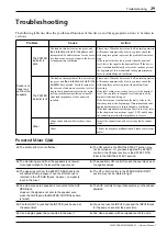
Page 29: ... external effect processor Follow the steps below 1 Raise the EFF 1 or EFF 2 controls for the channels to which you want the external effect to be applied 2 Adjust the level of the signal output to the external effects processor so that the sound will not be distorted at the input of the external effects processor 3 Use the control of the ST SUB IN channel to which the processed signal is input fr...

Page 30: ...peaker system If you are using a sub woofer press the LPF ON OFF switch located in the lower right of the EMX5000 20 EMX5000 12 to send the low range signal to the sub woofer The frequency range below the frequency spec ified by the control knob 80 120 Hz will be output to the sub woofer Main speakers Power AMP Subwoofer ...

Page 31: ...r to the peak level indicators of the main section when doing so If the device is not ventilated sufficiently refer to the cautions given at the beginning of this manual and take appropriate measures to insure adequate ventilation If the load impedance including a short is too low refer to the chapter on connections page 19 20 and change the connections so that the impedance is correct Other Conne...

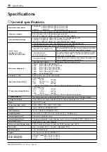
Page 32: ...to AUX SEND PRE 90 dB INPUT A B to AUX SEND POST 78 dB INPUT A B to EFFECT SEND 58 dB ST CH IN to ST OUT Crosstalk at 1 kHz 68 dB adjacent input 68 dB input to output Input channel equalization 15 dB Maximum HIGH 10 kHz shelving MID 250 Hz 5 kHz peaking LOW 100 Hz shelving Turn over roll off frequency of shelving 3 dB below maximum variable level ST Input channel equalization 15 dB Maximum HIGH 10...

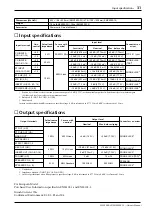
Page 33: ...dB 123 mV 4 dB 1 23 V ST INPUT CH9 12 17 20 34 10 kΩ 54 dB 1 55 mV 34 dB 15 5 mV 14 dB 155 mV PHONE JACK3 3 Unbalanced In these specifications when dB represents a specific voltage 0 dB is referenced to 0 775 Vrms 0 dBV is referenced to 1 Vrms 10 10 dB 245 mV 10 dB 2 45 V 30 dB 24 5 V ST SUB IN 1 2 12 dB 195 mV 4 dB 1 23 V 20 dB 7 75 V 2TR IN L R 26 dBV 50 1 mV 10 dBV 316 mV 10 dBV 3 16 V PHONO JA...

Page 34: ...n the devices Use a blank panel with holes for ventilation if you wish to insert a panel between the devices You will need a 13U space to install the rack mount Attaching the rack mount hardware 1 Remove the side panel together with the six screws indicated by arrows in diagram 1 below 2 Fasten the rack mount hardware using screws at the locations indicated by arrows in diagram 2 1 or 2 2 The heig...

Page 35: ...ONO OUT 4dB 10dB MONO OUT BA BA AUX SEND1 4dB AUX SEND2 4dB 10dB AUX1 10dB AUX2 AFL AFL AFL SUM SUM SUM 0dB SUM 0dB SUM 0dB 0dB 0dB SUM 0dB SUM SUM SUM 6dB SUM 6dB SUM 0dB SUM 0dB INV 0dB INV 0dB PFL POST POST BAL EFFECT1 EFFECT2 AUX1 AUX2 0dB 6dB 6dB 6dB 6dB DN BA BA 0dB 0dB 10dB ST CH Fader PEAK SIGNAL GAIN 34 10dB ST CH INPUT 34 10dB EMX5000 12 CH9 L 10 R CH11 L 12 R EMX5000 20 CH17 L 18 R CH19...

Page 36: ......

Page 37: ......

Page 38: ...YAMAHA CORPORATION V821290 R0 1 AP 36 Pro Audio Digital Musical Instrument Division P O Box 3 Hamamatsu 430 8651 Japan NP Printed in Taiwan ...

Reviews: