44
DXS12/DXS15
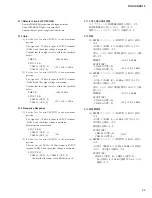
2-14. Total Harmonic Distortion
Set the level control (INPUT) to the maximum position.
When the signal is input to the INPUT terminal (XLR) L.
The following outputs are obtained, total harmonic
distortion is measured.
SP OUT (LF)
CN609-1 (OUT+_L), CN609-3 (OUT-_L)
+11.24±0.5 dBu : THD+N=0.5 % or less.
2-15. Maximum Output
When the sine wave is input to the INPUT terminal (XLR)
L.
The following outputs are obtained, total harmonic
distortion is measured.
SP OUT (LF)
CN609-1 (OUT+_L) +38.24 dBu +0.2 dBu
: THD+N=1 % or less.
CN609-3 (OUT-_L) +38.24 dBu -0 dBu
: THD+N=1 % or less.
* Measure this inspection within 5 seconds.
2-16. Confi rming the Excessive Output
Set the level control (INPUT) to the maximum position.
When the signal of 50 Hz 10 cycle +10 dBu is input to the
INPUT terminal (XLR) L.
Afterwards, the signal of -10 dBu is input to INPUT
terminal (XLR) L, and the output voltage is measured.
Con
fi
rm that the following output voltages should be able
to be measured without the power supply shutting down.
SP OUT (LF)
CN609-1
(OUT+_L)
:
+27.3 +3.0/-1.0 dBu
CN609-3
(OUT-_L)
:
* After clause 2-15 is inspected, it is necessary to inspect
clause 2-16.
2-17. Output noise level
Perform measurement with no signal input.
Set the level control (INPUT) to the maximum position.
INPUT terminal (XLR) is grounded through the resistor of
150
Ω
, the noise level generated in the output terminal is
measured.
Con
fi
rm that the output noise level is within the speci
fi
ed
below.
SP OUT (LF)
CN609-1 (OUT+_L)
:
-58 dBu or less
CN609-3 (OUT-_L)
:
2-14. 全高調波歪率測定
LEVEL コントロール(INPUT)を最大に設定します。
入力端子(XLR)L に信号を入力します。
以下の出力を得た時、全高調波歪率を測定します。
SP OUT (LF)
CN609-1 (OUT+̲L)、CN609-3 (OUT+̲L)
+11.24 ± 0.5 dBu
: THD+N=0.5 %以下
2-15. 最大出力
入力端子(XLR)L に正弦波を入力します。
以下の出力を得た時、全高調波歪率を測定します。
SP OUT (LF)
CN609-1 (OUT+̲L)
+38.24 dBu
+0.2 dBu
: THD+N=1 %以下
CN609-3 (OUT-̲L)
+38.24 dBu
-0 dBu
: THD+N=1 %以下
※この検査は 5 秒以内に測定してください。
2-16. 過大出力の確認
LEVEL コントロール(INPUT)を最大に設定します。
入力端子(XLR)L に 50 Hz 10 cycle +10 dBu の信号
を入力します。
その後、入力端子(XLR)L に -10 dBu の信号を入力
し、出力電圧を測定します。
電源がシャットダウンせず、以下の出力電圧が得ら
れることを確認します。
SP OUT (LF)
CN609-1 (OUT+̲L)
:
+27.3 +3.0/-1.0 dBu
CN609-3 (OUT-̲L)
:
※ 2-16 項の検査は、必ず 2-15 項(最大出力検査)
後に行ってください。
2-17. 出力ノイズレベル
測定は入力無信号の状態で行います。
LEVEL コントロール(INPUT)を最大に設定します。
入力端子(XLR)を 150 Ωの抵抗を介して接地し、
出力端子に発生するノイズレベルを測定します。
出力ノイズレベルが下記の規定範囲内にあることを
確認します。
SP OUT (LF)
CN609-1 (OUT+̲L)
:
-58 dBu 以下
CN609-3 (OUT-̲L)
:
Summary of Contents for DXS Series
Page 6: ...DXS12 DXS15 6 O 03 66 0 アンプAss y 1 DC ファン 68 68 68 68 036 63 ...
Page 7: ...7 DXS12 DXS15 DIMENSIONS 寸法図 478 618 624 397 563 594 DXS12 DXS15 Unit 単位 mm Unit 単位 mm ...
Page 21: ...21 DXS12 DXS15 Pattern side パターン側 AMPSW Circuit Board Scale 90 100 2NA WW65240 2 ...
Page 23: ...23 DXS12 DXS15 2NA WW59820 3 Pattern side パターン側 DSPW Circuit Board to AMPSW CN255 ...
Page 58: ...190 170 160 200 220 230 250 360 370 350 370 210 10d 240 Details A A 部詳細 380 7 DXS12 DXS15 ...
Page 59: ... E E F F D F E E E E E E E D E E 6 66 0 シールド Ass y 03 29 5 66 0 アンプカバー Ass y DXS12 DXS15 8 ...


