background image

DXR15/DXR12/DXR10/DXR8/DXS15/DXS12 Owner’s Manual

7

Controls and Functions

English

Controls and Functions

Rear panel

1

INPUT jacks

These are balanced XLR input jack(s) (INPUT 1), unbalanced 

phones (INPUT 2) and RCA pin input jacks (INPUT 3).

You can connect a mixing console or microphone to INPUT 

1, a keyboard or electric-acoustic guitar to INPUT 2, and a 

portable audio player or CD player to INPUT 3. Signals from 

INPUT 1-3 are mixed inside the DXR unit.

The DXS series input features only balanced XLR input jacks 

(L, R). L and R signals are mixed inside the DXS unit.

2

THRU jack(s)

These are balanced XLR output jack(s). Input signals will be 

passed through unaffected, since these are parallel 

connected to the INPUT jacks.

3

LEVEL control

Adjusts the level of each INPUT signal. If you connect a 

device that features a nominal output level of +4dBu (such as 

a mixing console), set the MIC/LINE switch (

9

) on the DXR 

series to LINE, and adjust the LEVEL control using its 12 

o’clock position as a reference.

4

LIMIT indicator

Lights when the output limiter is active. The output limiter will 

operate in order to protect the speaker and amp, attenuating 

the output signal to the amplifier. If this indicator stays lit, 

lower the level of the input signal.

NOTE

If the output voltage of the amplifier has exceeded the maximum 
value, or if excessive integral power consumption is detected, the 
LIMIT indicator will light when the amount of attenuation is 3dB or 
higher.

The integral power consumption refers to the sum of power 
consumption provided to the speaker driver per unit time.

5

SIGNAL indicator

Lights when an audio input signal is detected.

6

PROTECTION indicator

Lights when the protection system is active. The protection 

system will operate and the speaker output will be muted in 

the following situations.

• If amplifier overheatin

g

 is detected:

• If DC output is detected:

• If overcurrent is detected:

When turnin

g

 the power on:

The protection system will be activated to prevent noise and
the indicator will light for about two seconds. The indicator
turns off when the power supply has started normally.

When turnin

g

 the power off:

Or if the power turns off due to an unexpected error, the
protection system will be activated to prevent noise, and then
the power will be shut down.

NOTE

If the protection system has engaged after the problem was 
detected, waiting until the amplifier cools down or powering off and 
on again will return to normal operation. If the unit does not return to 
normal operation, please contact your Yamaha dealer.

)

@

#

4

5

6

7

8

4

5

6

7

8

!

%

^

9

3

3

1

1

1

1

1

2

1

1

1

2

3

3

3

3

3

$

DXR15, DXR12, DXR10, DXR8

DXS15, DXS12

Summary of Contents for DXR Series

Page 1: ...ANLEITUNG MODE D EMPLOI MANUAL DE INSTRUCCIONES MANUALE DI ISTRUZIONI English Deutsch Français Español Italiano YAMAHA POWERED SPEAKER eries DXR8 DXR1O DXR12 DXR15 POWERED SUBWOOFER DXS12 DXS15 Series PYKOBOQCTBO FIOTI b3OBATEJ lFl EH3 iiiEH HY1 Fé 3H ...

Page 2: ... type plug has two blades and a third grounding prong The wide blade or the third prong are provided for your safety If the provided plug does not fit into your outlet consult an electrician for replacement of the obsolete outlet 10 Protect the power cord from being walked on or pinched particularly at plugs convenience receptacles and the point where they exit from the apparatus 11 Only use attac...

Page 3: ...pe cable If these corrective measures do not produce satisfactory results please contact the local retailer authorized to distrib ute this type of product If you can not locate the appropriate retailer please contact Yamaha Corporation of America Electronic Service Division 6600 Orangethorpe Ave Buena Park CA90620 The above statements apply ONLY to those products distrib uted by Yamaha Corporation...

Page 4: ...ersonnel The power cord or plug becomes frayed or damaged It emits unusual smells or smoke Some object has been dropped into the instrument There is a sudden loss of sound during use of the device If this device should be dropped or damaged immediately turn off the power switch disconnect the electric plug from the outlet and have the device inspected by qualified Yamaha service personnel CAUTION ...

Page 5: ...per plastic metal etc into any gaps or openings on the device panel If this happens turn off the power immediately and unplug the power cord from the AC outlet Then have the device inspected by qualified Yamaha service personnel Do not rest your weight on the device or place heavy objects on it and avoid use excessive force on the buttons switches or connectors Do not use the device for a long per...

Page 6: ...OR mode that has been optimized for use as a floor monitor Select the mode that suits your application D XSUB DXS series D XSUB is a newly developed processing technology exclusively for subwoofers that dynamically controls the low frequency range It features a BOOST mode that enhances and provides punch to the sound and an XTENDED LF mode that extends the bottom of the low frequency range You can...

Page 7: ... the level of the input signal NOTE If the output voltage of the amplifier has exceeded the maximum value or if excessive integral power consumption is detected the LIMIT indicator will light when the amount of attenuation is 3dB or higher The integral power consumption refers to the sum of power consumption provided to the speaker driver per unit time 5 SIGNAL indicator Lights when an audio input...

Page 8: ...d from each INPUT jack to a connected DXR series speaker Connect this jack to the INPUT 1 XLR jack on the linked DXR series speaker Signals at the LINK OUT jack are line level Set the MIC LINE switch on the linked DXR series speaker to LINE For stereo signals set the LEVEL control on the linked DXR to the 12 o clock position to balance the levels between two DXRs LINK MODE switch DXR series Enable...

Page 9: ...ng toward the floor by 7 degrees Suspended installation If you plan to suspend your DXR series speaker attach commercially available eye bolts to the screw holes which are sealed at the time of shipment located on the top two locations and on the lower part of the rear one location The size of the screw holes on the DXR15 and DXR12 is M10 for an eye bolt length of 18mm or less The size of the scre...

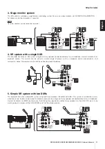
Page 10: ...rship and an event site We recommend that the subwoofer s input LEVEL control is set to a 12 o clock position If you prefer you can adjust the level as desired As necessary add a stage monitor system illustrated in no 3 NOTE Pole sockets for mounting speaker poles are provided at the bottom of the DXR series and at the top of the DXS series Please refer to the Precautions page 4 If you use multipl...

Page 11: ...k source This system can be used in a wide range of places such as corporate events presentations and restaurants Adjust the volume with the LEVEL control to prevent feedback 5 Simple SR system with two DXRs This example illustrates a simple SR system using two 2 way speakers linked to each other This system is suitable for a small sized live venue Audio can be output in stereo or monaural by usin...

Page 12: ...me of the input device and locate the microphone more closely to the sound source The setting of the HPF switch is not appropriate Set the HPF switch on 120Hz or 100Hz if you get feedback in low frequency bands Each speaker sound differs if multiple speakers are used Settings for each speaker differ DXR series Set the HPF and D CONTOUR switches of each speaker to the same positions DXS series Set ...

Page 13: ...x 24 1 2 397 563 594 mm 15 5 8 x 22 1 8 x 23 3 8 Net Weight 22 5kg 49 6lbs 19 3kg 42 5lbs 14 6kg 32 2lbs 13 5kg 29 8lbs 38 0kg 83 8lbs 33 0kg 72 8lbs Handles Aluminium die cast Side x 2 Aluminium die cast Top x 1 Metal Side x 2 Pole Socket 35mm with 2 way feature 0 or 7 degree 35mm Top Rigging points Top x 2 Rear x 1 Fits for M10 x 18mm eyebolts Top x 2 Rear x 1 Fits for M8 x 15mm eyebolts Optiona...

Page 14: ...t Sensitivity LEVEL Center INPUT1 LINE 11dBu MIC 22dBu 11dBu INPUT2 3 3dBu Maximum Input Level INPUT1 LINE 24dBu MIC 20dBu 24dBu INPUT2 3 16dBu Controls LEVEL x3 LINE MIC HPF D CONTOUR FRONT LED DISABLE LINK MODE POWER LEVEL POLARITY LPF D XSUB FRONT LED DISABLE POWER Idle Power Consumption 35W 1 8 Power Consumption 110W 90W 120W Power Requirements 100V 240V 50Hz 60Hz Amplifier DXR15 DXR12 DXR10 D...

Page 15: ...DXR8 DXS15 DXS12 Owner s Manual References Italiano Español Français Deutsch English Dimensions DXR8 280 280 458 DXR12 362 350 601 402 5 0 DXR10 305 310 355 5 0 502 DXR15 445 380 456 700 5 0 Unit mm Unit mm Unit mm Unit mm ...

Page 16: ...DXR15 DXR12 DXR10 DXR8 DXS15 DXS12 Owner s Manual 83 References Italiano Español Français Deutsch English DXS12 DXS15 Unit mm Unit mm 478 618 624 397 563 594 ...

Page 17: ...TION LOGIC EQ EQ MONITOR D CONTOUR FOH MAIN OFF HPF 100Hz OFF L MONO R L R 2 LINE 3 LINE HA HA HA HA HA LINK OUT LINE HF LF LEVEL LEVEL LEVEL INPUT AD DA DA DSP HF LF MONO INPUT1 2 L R 3 L R STEREO INPUT1 2 R 3 R MONO INPUT1 2 L R 3 L R STEREO INPUT1 2 L 3 L INPUT MIX LINK MONO STEREO 120Hz SIGNAL DELAY AMP TEMP DC FAULT OUTPUT CURRENT OUTPUT VOLTAGE INTEGRAL OUTPUT POWER ON OFF MUTE PROTECTION LO...

Page 18: ...a santé humaine qui pourraient advenir lors d un traitement inapproprié des déchets Pour plus d informations à propos de la collecte et du recyclage des déchets d équipements électriques et électroniques veuillez contacter votre municipalité votre service de traitement des déchets ou le point de vente où vous avez acheté les produits Pour les professionnels dans l Union Européenne Si vous souhaite...

Page 19: ...ea Econômica Européia Για λεπτομερείς πληροφορίες εγγύησης σχετικά με το παρόν προϊόν της Yamaha και την κάλυψη εγγύησης σε όλες τις χώρες του ΕΟΧ και την Ελβετία επισκεφτείτε την παρακάτω ιστοσελίδα Εκτυπώσιμη μορφή είναι διαθέσιμη στην ιστοσελίδα μας ή απευθυνθείτε στην αντιπροσωπεία της Yamaha στη χώρα σας επόμενη σελίδα ΕΟΧ Ευρωπαϊκός Οικονομικός Χώρος För detaljerad information om denna Yamah...

Page 20: ...MK7 8BL United Kingdom Tel 353 0 1526 2449 Fax 44 0 1908 369278 ITALY Yamaha Musica Italia s p a Viale Italia 88 20020 Lainate Milano Italy Tel 39 0 02 93577 1 Fax 39 0 02 937 0956 LATVIA Yamaha Music Europe GmbH Sp z o o Oddział w Polsce Branch Poland ul 17 Stycznia 56 PL 02 146 Warszawa Poland Tel 48 0 22 500 29 25 Fax 48 0 22 500 29 30 LIECHTENSTEIN Yamaha Music Europe GmbH Rellingen Branch Swi...

Page 21: ...ate Milano Italy Tel 02 935 771 SPAIN PORTUGAL Yamaha Music Europe GmbH Ibérica Sucursal en España Ctra de la Coruna km 17 200 28231 Las Rozas Madrid Spain Tel 34 91 639 88 88 GREECE Philippos Nakas S A The Music House 147 Skiathou Street 112 55 Athens Greece Tel 01 228 2160 SWEDEN FINLAND ICELAND Yamaha Music Europe GmbH Germany filial Scandinavia J A Wettergrensgata 1 Box 30053 S 400 43 Göteborg...

Page 22: ... INSTRUCCIONES MANUALE DI ISTRUZIONI C S G PA Development Division 2011 2013 Yamaha Corporation 311YJCR C0 Printed in China ZA97860 Yamaha Pro Audio global website http www yamahaproaudio com Yamaha Manual Library http www yamaha co jp manual English Deutsch Français Español Italiano ...

Reviews: