


DVD-S510/DV-S5350
20
■
TROUBLESHOOTING
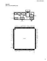
Display board
DISPLAY PCB OK.
NO DISC
POWER ON
DISPLAY?
Check presence of high pulses at pin 23 of IC7104 while pressing a key on remote control.
Check IR receiver 7110.
Check safety resistor R3131.
Diagnostic
software
“Player script” : Remote control test.
Check if voltage at connector 1117-1 is 4.9V when power on (no light)
Check if voltage at base of Tr 7109 is 4.9V when power on (no light).
Check if voltage at connector 1117-1 is 3.33V during standby (light).
Diagnostic
software
“Player script” : LED test.
Check matrix scanning at pin 36 and 37: see test instructions.
Check matrix scanning at pin 26,27,28,29,30,31,32,33.
Diagnostic
software
“Player script” : Keyboard test.
Check
supply
voltages
The display pcb uses a 24V stabiliser(7112) in combination with a 10V zener diode(6102).
Check input voltage: at connector 1115-4:
-40V 5%
Check output voltage at anode of Diode 6102:
-10V 5%
Check stabilizer 7112 output (VKK):
-34V 7%
Check +5Vstb voltage at connector 1115-3:
+5V 5%
Check safety resistor R3117
Check +12V at connector 1115-1:
+12V 10%
Check
filament
voltage
AC voltage is created via uP output pin 19 generating a 42kHz (duty cycle 45/55) square
signal.
Check frequency : 42kHz 10%
Check buffered square output at emitter of transistor 7105; low level: 800mV, high level:
10.7V
Check DC decoupling: check RMS voltage between FIL1 and FIL2 lines:
3.9Vrms<Vfil<5.2Vrms
The Vfil_DC level at kathode of diode 6101 should be –25.8V 10%
Check oscillator frequency of 8MHz at pin 8 of IC7104
Check reset circuit around transistor 7108: see test instructions of reset circuit.
Check timing and level for all grid lines(G1
G14): see test instructions grid lines.
Check timing and level of segment lines(P1
P10): see test instructions segment lines.
Diagnostic
software
“Player script” : Display test.
NO
YES
Key Function
NO
YES
Standby LED off?
YES
Remote control?
NO
YES
NO
Summary of Contents for DVD-S510
Page 5: ...DVD S510 DV S5350 4 FRONT PANELS DVD S510 DV S5350 REMOTE CONTROL TRANSMITTER...
Page 47: ...A B C D E F G H I J 1 2 3 4 5 6 7 DVD S510 DV S5350 53 52 PRINTED CIRCUIT BOARD MONO Top view...
Page 50: ...A B C D E F G H I J 1 2 3 4 5 7 DVD S510 DV S5350 6 59 58 PRINTED CIRCUIT BOARD A V U C A R T...
Page 51: ...A B C D E F G H I J 1 2 3 4 5 6 7 DVD S510 DV S5350 _Z _A 61 60 PRINTED CIRCUIT BOARD A V B G...
Page 52: ...A B C D E F G H I J 1 2 3 4 5 7 DVD S510 DV S5350 6 63 62 PRINTED CIRCUIT BOARD DISPLAY...
Page 53: ...A B C D E F G H I J 1 2 3 4 5 6 7 DVD S510 DV S5350 65 64 PRINTED CIRCUIT BOARD POWER B G...