background image

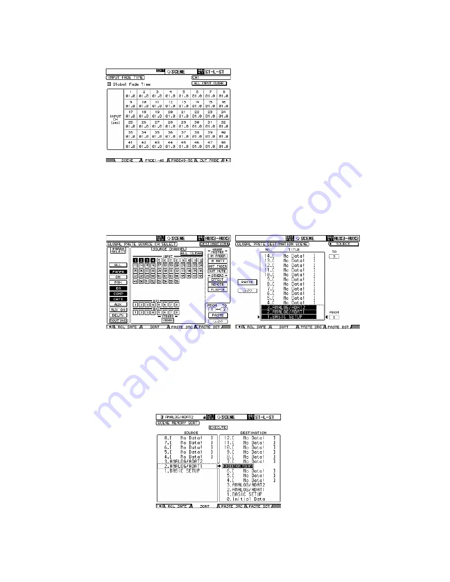
SCENE FADE 


Normally when a Scene is recalled, the 
Faders move instantly to their stored 
position.  Using the Fade Time function, 
the faders can be programmed to move 
slowly, taking up to 30 seconds to 
complete their movement.  Checking the 
Global Fade Time box will give the same 
Fade Time to every Scene.  After setting 
the Fade Time for one channel, double-
click the ENTER switch to copy the time to 
all Input or Output Channels. 


SCENE COPY / PASTE


If some settings need to be copied from one Scene to some others, the 
PATSE SRC and PASTE DST LCD screens can be used. 


In the PASTE SRC screen, choose which parameters of which 
channels should be copied. 
In the PASTE DST screen, choose which Scene Memories should be 
updated.  The maximum number is 10 Scenes for each operation. 
 
To move a Scene to a different position in the Library, use the SORT 
screen in the SCENE MEMORY menu: 


18 


02R96-v2 Quick Start Guide 

Summary of Contents for DM1000-v2

Page 1: ...02R96 v2 Quick Start Guide 1 02R96 v2 Quick Start Guide ...

Page 2: ... to do this if you have just unpacked the product from its box for the first time To start from blank settings without erasing the memories just recall SCENE 00 To do this use the SCENE MEMORY Up Arrow Down Arrow switches to select Scene 00 and then press RECALL All the faders will then move down and all the mixing functions set to their default status 2 02R96 v2 Quick Start Guide ...

Page 3: ... Stereo Studio and Control Room outputs 5 3x 2 Track Digital Inputs and Outputs 6 4 option slots for expansion 4 2 5 3 1 6 Other connectors on the rear panel are for various control and sync functions For example the CONTROL port 25 pin D sub is for low voltage GPI relays The CASCADE IN and OUT ports are for connecting with other 02R96 consoles to share audio buses The METER connector is for the o...

Page 4: ...ay Access switches grey diamond shapes 8 Machine Control and Display control switches 1 2 3 7 8 8 6 4 3 5 The SELECTED CHANNEL area is a fundamental concept to understand It shows all the important functions for one channel at a time Only one channel can be selected at any time To select a channel and see its settings in the SELECTED CHANNEL area just press the SEL switch Then press the SEL switch...

Page 5: ...st change which channels you are looking at Each fader controls a different input to the 02R96 This assignment is not fixed it can be changed in the INPUT PATCH menu Here is the default patch channels 1 24 control the 24 analog inputs on the top on the console channels 25 32 control inputs 1 8 from Slot 1 channels 33 40 control inputs 1 8 from Slot 2 channels 41 48 control inputs 1 8 from Slot 3 c...

Page 6: ...ve the cursor on the screen to the required channel number 4 Press ENTER by the data wheel at the bottom right corner of the console 5 Select the type of input from the first list AD in Slot in FX out and so on 6 Press ENTER and choose the required item from the next column Slot or FX for example 7 Press ENTER and choose the required item from the last column CH or L R for example 8 Press ENTER an...

Page 7: ...n a pop up window 3 To see the Aux send information for many channels at the same time press the AUX SELECT DISPLAY switch Each time this switch is pressed it will change the LCD to a different page to see the information for other channels In these pages Pre Post status can be edited and the Aux sends can be switched off by pressing ENTER while the cursor is high lighting the level encoder 4 When...

Page 8: ...l show the EQ edit screen There are 4 parametric bands To change between controlling FREQUENCY and Q press down quickly on the encoder Note that the LOW band can be a Low Shelf or a HPF by changing the Q to the maximum or minimum position In the same way the HIGH band can be a High Shelf or a LPF There are 2 types of EQ TYPE I or TYPE II with slightly different sound characteristics The ATT functi...

Page 9: ...t eq or post fader PAN The PAN and SURROUND PAN settings of the selected input channel can be edited here Output channels do not have Pan The L and R switches show if the channel is the Left or Right side of a stereo pair The Joystick is not active until a surround mode is selected To do this press the PAN SURROUND DISPLAY switch so the SURR MODE page is shown Then choose the SURROUND MODE 3 1 or ...

Page 10: ...hat the PAN of the channel will follow through to the Buses This is particularly useful when using the Buses as stereo sub groups as on a typical analog console Buses can be routed to Stereo just like Sub Groups on an analog console To do this press the ROUTING DISPLAY switch to see the BUS TO ST screen Here Buses 1 8 can be routed panned and mixed to the Stereo Bus Use the cursor keys data wheel ...

Page 11: ...anged here DELAY Press this DISPLAY ACCESS switch to see Delay settings for each channel All input and output channels have a delay function The maximum possible delay time varies with sample rate At 44 1KHz the maximum possible delay time is 984 1ms Input channels have a FB GAIN Feedback Gain and MIX parameter to create a simple delay effect The DELAY SCALE can be changed to see the delay time in...

Page 12: ...r layer 1 24 to be paired with the equivalent channel on the layer below 25 48 Channels 49 56 and the output channels can only be paired Horizontally When channels are paired they share the same fader level the same ON EQ Gate Comp Aux settings Pan and Routing parameters remain separate To quickly pair channels without using the LCD screen first 1 hold down the SEL switch for the Left channel then...

Page 13: ...moved without the others then hold that channel s SEL switch while pushing the fader but not while the GROUP menu is displayed or the channel will be removed from the Group Channels cannot be in more than one Fader Group at the same time MUTE GROUPS Mute Groups are useful for switching On Off many channels by just pressing one switch There are 8 Mute Groups available for input channels and 4 Mute ...

Page 14: ...s below the LCD Use the Up Down arrow switches next to these encoders to move to the other rows of parameters when an effect has more than 4 parameters to edit To change the type of effect from Reverb to Delay for example press the EFFECTS PLUG INS DISPLAY switch to see the FX LIBRARY Then scroll through the list with the data wheel and press ENTER with the cursor over the RECALL button on the lef...

Page 15: ...spectively This is convenient but can be changed if necessary For example an effect could be inserted in just one channel using the INSERT OUT and IN patch To change the FX patching go to the EFFECT1 4 page in the INPUT PATCH display menu ROUTING AUDIO THROUGH AN EFFECT 1 First audio needs to be routed into the effect If the default patch is used first turn up Aux 1 send level for the required cha...

Page 16: ...efault position 3 Already audio should be seen on the level meters of Effect 1 You can see the meters on the top right corner of the FX EDIT screen 4 Then push up faders 49 and 50 to start hearing the effect s output in the Stereo bus 16 02R96 v2 Quick Start Guide ...

Page 17: ...l if different Scenes need different Patch settings Patch information is not stored in the scenes but is stored in the INPUT PATCH and OUTPUT PATCH libraries accessed from the relevant DISPLAY ACCESS switches Then the Patch libraries can be linked to the Scenes so they are recalled at the same time as the scene RECALL SAFE In this screen choose which parameters will not be over written when recall...

Page 18: ...ouble click the ENTER switch to copy the time to all Input or Output Channels SCENE COPY PASTE If some settings need to be copied from one Scene to some others the PATSE SRC and PASTE DST LCD screens can be used In the PASTE SRC screen choose which parameters of which channels should be copied In the PASTE DST screen choose which Scene Memories should be updated The maximum number is 10 Scenes for...

Page 19: ...the Studio monitors Pressing the CONTROL ROOM switch will route the Control Room signal also to the Studio 4 The SOLO CLEAR switch will switch off the SOLO switches for all channels 5 The MONITOR DISPLAY switch accesses the many extra monitor functions on the LCD 2 4 3 5 1 There is a small TALKBACK microphone built in to the top right corner of the console and it has a level controller The TALKBAC...

Page 20: ...Y NOTE __________________________________________________ The parameters which are copied are determined on the PREFERENCES 2 page in the SETUP menu Other Short Cuts 1 EQ Gain to 0dB To reset the gain of an EQ band to 0dB press and hold the Freq Q encoder for one second 2 EQ Reset To return the whole Parametric EQ for a channel to its default settings press the Freq Q encoders for the LOW and HIGH...

Page 21: ... quick headphone mix in a recording session where AUX 7 and 8 can be sent directly to the STUDIO MONITOR OUT or making a quick stage monitor mix for a guest musician at a live performance 6 SCENE FADE TIME Copy To assign the same fade time to all channels first enter the required FADE TIME for one channel then double click ENTER to copy the time to all the other input or output channels Other Tips...

Page 22: ... memorised just before the next Scene is recalled Then when a previous Scene is recalled its last settings are recalled first Press RECALL again to access the original scene settings So two memories for each scene are kept the original settings and the last settings 6 Return to Current Scene When scrolling through the SCENE MEMORY list it is easy to forget which is the current Scene To force the d...

Page 23: ...ove the SURROUND MONITOR LEVEL encoder 9 USER DEFINED KEYS Here are some suggested uses for these keys apart from the defaults Scene 1 1 Recall to recall the next or the previous Scene OSC On Off to control the internal Oscillator Talkback Assign to choose the talkback destination Studio Manager open and close various windows in the 02R96 Editor software on PC or Mac 10 Initialize Memories To eras...

Reviews: