For Service Engineer
Service Information
SI1604009E-002= S20, S10, M20, M10 and D10 installation procedures
20/34
3.9 Lock adjuster bolts and support legs
Step 1. Fine adjust the machine levelness.
After removing the hydraulic jack from the machine base, fine adjust the adjuster bolts. Then fine
adjust the levelness, the transfer height and the position of the production line.
Step 2. Make sure that the pressure intensity of the 4 adjuster bolts are the same.
Make sure that one person checks the pressure intensity of the blots and lock the lock nut to
prevent the variation.
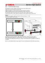
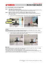
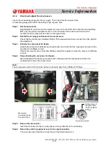
1) Fix the wrench of the adjuster bolt side. Then turn the lock nut to tighten (4 adjuster bolts).
Caution:
When tightening the lock nut, the transfer height rises by the amount of backlash of the screw. (Approx.
0.5mm) *The specified value of the tightening torque: 700N.m
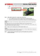
2) Tap the part of the adjuster bolts that contact the floor with a wrench or a copper hammer to
make sure that they are grounded firmly on the floor.
Reference:
Tap several different points on the bolts. If the tapping sound echoes throughout the machine, it indicates
that the adjuster bolts are not firmly grounded on the floor.
If the pressure intensity of the bolts is appropriate, only the leveling bolt part makes the noise.
(* The perception of the noise varies depending on the individual. Also the noise varies depending on the
weight of the machine and the position of the center of gravity.)
Lock nut
Adjuster bolt

