15
CRX-330/NS-BP110/NS-BP100
CRX-330/
NS-BP1
1
0/NS-BP1
0
0
CRX-330
Top cover ass’y
トップカバーASSY
Front panel unit
フロントパネルユニット
Hook
フック
Hook
フック
MAIN (2) P.C.B.
MAIN (1) P.C.B.
POWER (2) P.C.B.
CB704
CB703
CB207
W801
CB801
1
1
3
3
2
2
5
4
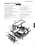
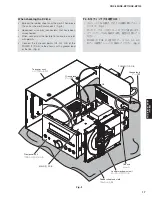
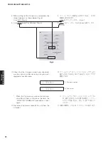
Fig. 1
■
DISASSEMBLY PROCEDURES /
分解手順
(番号順に部品を取り外してください。)
AC 電源コンセントから、電源コードを抜いてください。
1. トップカバー ASSY の外し方
a. ①のネジ 4 本、②のネジ 4 本を外します。(Fig. 1)
b. トップカバー ASSY を持ち上げます。(Fig. 1)
c. CB703、CB704 を外します。(Fig. 1)
d. トップカバー ASSY を取り外します。(Fig. 1)
※ ト ッ プ カ バ ー ASSY を 取 り 付 け る 場 合、 配 線 が
ローダーメカユニットのディスクトレイや POWER
P.C.B. に接触しないよう十分注意してください。
2. フロントパネルユニットの外し方
a. ③のネジ 2 本、④のネジ 2 本を外します。(Fig. 1)
b. ⑤のネジを外し、W801 を外します。(Fig. 1)
c. CB801 を外します。(Fig. 1)
d. フック 2 ヶ所を外し、フロントパネルユニットを外
します。(Fig. 1)
e. CB207 を外します。(Fig. 1)
(Remove parts in the order as numbered.)
Disconnect the power cable from the AC outlet.
1. Removal of Top Cover Ass’y
a. Remove 4 screws (
➀
) and 4 screws (
➁
). (Fig. 1)
b. Lift the top cover ass’y. (Fig. 1)
c. Remove CB703 and CB704. (Fig. 1)
d. Remove the top cover ass’y. (Fig. 1)
*
When installing the top cover ass’y, be careful not to
allow its cables to touch the disc tray of the loader
mechanism unit and the POWER P.C.B..
2. Removal of Front Panel Unit
a. Remove 2 screws (
➂
) and 2 screws (
➃
). (Fig. 1)
b. Remove screw (
➄
) and then remove W801. (Fig. 1)
c. Remove CB801. (Fig. 1)
d. Release 2 hooks and then remove the front panel
unit. (Fig. 1)
e. Remove CB207. (Fig. 1)

