background image

Installation

 Additional Drive

Replacing Drive

About IDE 

2

Yamaha recommends you connect only the CRW8424E as a secondary master.

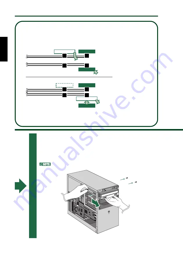
Example-2

If you disconnect the IDE 
device and re-connect it to 
another location, other 
devices connected to the 
IDE cable may become slow 
in processing, unstable, or 
inoperative.

If the 40-pin IDE cable has 
only one connector available 
but you wish to re-connect 
the IDE device (that you just 
disconnected) to another 
location, use a 40-pin IDE 
cable that has two 
connectors.

If you connect only one IDE 
device to an IDE cable, 
assign the device as a 
master and connect it to the 
end of the cable.

Example-1

IDE cable (Secondary)

No Device

(slave)

IDE cable (primary)

IDE device

IDE cable (Secondary)

No device

(slave)

(slave)

Connect.

Remove.

CRW8424E

(master)

Connect.

CRW8424E

IDE cable (primary)

CD-ROM Drive e.t.c.

(slave)

Remove the CD-ROM drive e.t.c. 
to replace it with the CRW8424E

Hard Disk

(master)

(master)

Hard Disk

(master)

CD-ROM Drive e.t.c.

6

Remove the four screws holding the CD-ROM drive in place,
then slide the drive forward and out of the drive bay.

Before removing the CD-ROM drive from the computer, make
sure that all the cables have been removed from the CD-ROM
drive’s rear panel.

Do not force pulling or apply excessive force to the CD-ROM drive.

13

Summary of Contents for CRW8424E Series

Page 1: ...IENUNGSANLEITUNG MODE D EMPLOI MANUAL DE INSTRUCCIONES CD R RW Drive CRW8424E SERIES OWNER S MANUAL BEDIENUNGSANLEITUNG MODE D EMPLOI MANUAL DE INSTRUCCIONES CD R RW Drive CRW8424E SERIES 8424S_e qx 9 8 99 3 40 PM Page 1 ...

Page 2: ... and found to comply with the requirements listed in FCC Regulations Part 15 for Class B digital devices Compliance with these requirements provides a reasonable level of assurance that your use of this product in a residential environment will not result in harmful interference with other electronic devices This equipment generates uses radio frequencies and if not installed and used according to...

Page 3: ...RUKSANVISNING SPECIFICERATS KAN ANVÄNDAREN UTSÄTTAS FÖR OSYNLIG LASERSTRÅLNING SOM ÖVERSKRIDER GRÄNSEN FÖR LASERKLASS 1 CLASS 1 LASER PRODUCT LASER KLASSE 1 PRODUKT LUOKAN 1 LASERLAITE PRODUIT LASER DE CLASSE 1 This device is classified as a CLASS 1 LASER product The CLASS 1 LASER PRODUCT label must be located on the exterior CAUTION INVISIBLE LASER RADIATION WHEN OPEN AVOID EXPOSURE TO BEAM VORSI...

Page 4: ......

Page 5: ...English i CD R RW Drive CRW8424E SERIES CD R RW Drive CRW8424E SERIES OWNER S MANUAL ...

Page 6: ...se there is an increased risk of personal injury electrical shock damage to the device or fire Please take particular care if small children are present Do not expose the device to rain use it near water or in damp or wet conditions or place containers on it that contain liquids which might spill into any openings Otherwise there is an increased risk of electrical shock fire or personal injury Fol...

Page 7: ...sc from the tray before transporting the device Otherwise written data may be destroyed When cleaning the device never use benzene paint thinners detergents or chemical impregnated wiping cloths Also do not place vinyl plastic or rubber objects on the device Otherwise the device may be damaged or its front panel may become discolored Use a soft dry cloth to wipe the device Do not rest your weight ...

Page 8: ... in part or in full is ex pressly forbidden Precautions forTransportation Before transporting the device always place the transportation pad on the disc tray and put the device back in its original box If the device is transported without adequate packing the internal components may be damaged and cause the device to malfunction Distributing Discs When writing important data or preparing data for ...

Page 9: ...rks are the property of their respective companies Table of Contents Setup Flowchart 1 Introduction 2 Features of the CRW8424E Drive 2 System Configuration 3 Computer 3 Software 3 Discs 4 Tools 5 Front and Rear of Unit 6 Front Panel 6 Rear Panel 7 Installation 8 First Steps 8 Installing the CRW8424E Drive 9 Operation 24 Loading a Disc 24 Ejecting the Disc 24 Ejecting a Disc in an Emergency 25 Trou...

Page 10: ...check that the drive is recognized correctly by the computer s OS P 23 STEP 3 Install the CD writing software For details about how to install the software refer to the documentation that came with it STEP 1 Set up the CRW8424E drive 1 Remove the outer casing of computer P 10 2 Set the jumper switches P 14 3 Fit the drive into the computer P 15 STEP 4 Start using the CRW8424E drive Use the drive t...

Page 11: ...of purposes such as backing up data writing your own audio CDs and creating multimedia titles using CD Extra mode Just choose the writing reading format that suits your needs For more details refer to page 4 Supports all Four CD Writing Modes These modes are Disc at Once the disc is written in a single pass without pausing as used for audio CDs and in premastering Track at Once data can be written...

Page 12: ...ust support the CRW8424E drive for writing to CD R or CD RW For details about how to install and use the software refer to the documentation that came with it When temporarily storing data on a hard disk prior to writing to CD R RW you will need an extra area of 50 100MB free hard disk space When creating an image file of the data on hard disk before writing to CD R RW you will need as much hard d...

Page 13: ...ines how all recordable discs including CD R and CD RW are written Part 2 of the Orange Book standard relates to CD R discs and Part 3 to CD RW discs The standard was named after the color of the book s pages Similarly the Red Book standard relates to audio CD DA discs and the Yellow Book standard relates to CD ROM discs About CD ROM A CD ROM disc is a compact disc containing high density read onl...

Page 14: ...ive You may also need to temporarily remove the sound card to gain access to the CD audio connectors In which case a small screw retaining the sound card s face plate has to be removed Make sure your screwdriver s head is the correct size for the screws you need to remove Long Nosed Pliers You will need these to insert or remove the plastic shunts when setting the jumper switches at the back of th...

Page 15: ...one volume control Adjust this control to set a suitable volume level when listening to an audio CD using the headphone jack Slide the knob to the left to decrease the volume and to the right to increase it ON DISC LED This LED is orange when the drive is powered on and green when the drive contains a disc READ WRITE LED This LED is green when data is being read off a disc and orange when data is ...

Page 16: ... IDE INTERFACE CONNECTOR 1 L G IO OUT 1MASTER jumper switch default setting Plug a plastic shunt into this jumper switch if you are connecting the master CRW8424E using an IDE cable 2SLAVE jumper switch Plug a plastic shunt into this jumper switch if you are connecting the slave CRW8424E using an IDE cable 3CSEL jumper switch If your computer supports the CSEL function plug a plastic shunt into th...

Page 17: ...ve out of its packaging you should immediately note down the serial number shown on the top of the drive together with a barcode You may need to refer to this number when requesting User Support services In the box below the following diagram write down the 10 character serial number consisting of 3 letters followed by 7 digits Drive s serial number 3 letters 7 digits Serial No 8 ...

Page 18: ...the computer s existing CD ROM drive CRW8424E As a replacement drive If the casing of your computer does not have a spare 5 25 inch drive bay available such as with many desktop type designs you can replace the computer s existing CD ROM drive with the CRW8424E drive CD ROM drive CRW8424E You cannot replace the computer s existing CD ROM drive with the CRW8424E using the existing cable if the driv...

Page 19: ... 2 Remove the outer casing of the computer If you need to remove screws in the process make sure you don t lose them The method for removing the casing and fitting the drive in the drive bay can vary depending on the manufacturer Refer to the documentation that came with your computer for further details 3 Touch a metal part of the computer s chassis or power supply unit to drain any static charge...

Page 20: ...e the front cover of a vacant 5 25 inch drive bay slot in the computer When you finish this step proceed to Step 7 on page 14 Front panel 5 25 inch drive bay slot Front cover 4 Remove the front panel of the computer Front panel 5 25 inch drive bay slot 11 ...

Page 21: ...f the devices connected via the IDE cable is called master and the other called slave IDE connectors on the motherboard PRIMARY IDE SECONDARY IDE IDE device slave IDE device slave IDE cable primary IDE cable secondary IDE device master IDE device master 5 Disconnect all the cables connected to the rear of the existing CD ROM drive and also disconnect the audio cable from the sound card or motherbo...

Page 22: ...e to an IDE cable assign the device as a master and connect it to the end of the cable Example 1 IDE cable Secondary No Device slave IDE cable primary IDE device IDE cable Secondary No device slave slave Connect Remove CRW8424E master Connect CRW8424E IDE cable primary CD ROM Drive e t c slave Remove the CD ROM drive e t c to replace it with the CRW8424E Hard Disk master master Hard Disk master CD...

Page 23: ...mper switches Plastic shunt Rear Panel The plastic shunts actually contain metal for bridging the two pins of a jumper switch creating an electrical connection between them when attached When removed the jumper switch is set to OFF Store unused plastic shunts in a safe place where they will not be lost Use a pair of long nosed pliers to attach or detach the plastic shunts accordingly However make ...

Page 24: ...placing Drive 8 Slide the drive backwards into the slot Do not apply excessive force when sliding the drive back into the drive bay slot 8 Slide the CRW8424E drive backwards into the now vacant bay without applying excessive force 15 ...

Page 25: ...er IDE and audio cables Then tighten the four fastening screws on the sides of the unit by hand to hold the drive in place 9 Leave enough room behind the drive to connect the power IDE and audio cables Then tighten the four fastening screws on the sides of the unit by hand to hold the drive in place 16 ...

Page 26: ...ction IDE INTERFAC E CONNECTOR DC INPUT 1 5V G 12V CSEL SLAVE MASTER AUDIO OUT R L G Colored line Primary connector Secondary connector 1 If an IDE cable has already been connected to the secondary IDE connector replace it with the included IDE cable If you wish to continue using the IDE device you just removed connect it to an available primary or secondary IDE connector When you connect two IDE ...

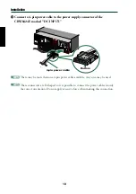
Page 27: ...lug is at the top IDE INTERFACE CONNECTOR DC INPUT 1 5V G 12V CSEL SLAVE MASTER AUDIO OUT R L G Sound card Vertically mounted type PH Horizontally mounted type MPC Audio cable Lug You do not need to connect the audio cable to write audio CDs since the audio is passed over the IDE bus It is required to play back audio CDs on the CRW8424E drive via the computer s sound card However if a CD ROM drive...

Page 28: ...DC INPUT 1 5V G 12V CSEL SLAVE MASTER AUDIO OUT R L G Top Top Bottom 4 pin power cable There may be more than one 4 pin power cable available Any one may be used These connectors are D shaped so it is possible to connect the power cables in only the correct orientation Do not apply excessive force when making this connection 19 ...

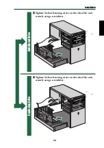
Page 29: ...on Additional Drive Replacing Drive Tighten the four fastening screws on the side of the unit securely using a screwdriver Tighten the four fastening screws on the side of the unit securely using a screwdriver 20 ...

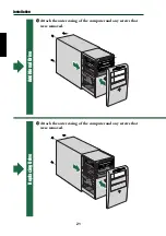
Page 30: ...Installation Additional Drive Replacing Drive Attach the outer casing of the computer and any screws that were removed Attach the outer casing of the computer and any screws that were removed 21 ...

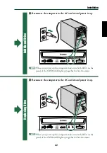
Page 31: ...r it up When you power up the computer make sure both LEDs on the panel of the CRW8424E light up together for brief moment Reconnect the computer to the AC outlet and power it up When you power up the computer make sure both LEDs on the panel of the CRW8424E light up together for brief moment 22 ...

Page 32: ...AHA CRW8424E Properties window and click the Settings tab to select it A screen similar to the one on the right appears Make sure that the Sync data transfer check box is not checked There is no need to set the Sync data transfer check box if it does not appear Make sure that the DMA check box is checked If it is not checked left click the box to select it If the DMA check box does not appear ther...

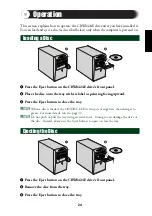
Page 33: ...l or printing facing upward 3 Press the Eject button to close the tray When a disc is loaded the ON DISC LED is lit up in orange first then changes to green For more details refer to page 32 Do not push or pull the tray using excessive force Doing so can damage the drive or the disc Instead always use the Eject button to open or close the tray Ejecting the Disc 1 2 1 Press the Eject button on the ...

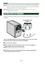
Page 34: ...mergency If the disc tray fails to open for some reason such as a power outage you can open it manually Manual Eject hole Paper Clip You should attempt to eject a disc manually only as a last resort Mal functions may occur if you do this too frequently 1 Power down the computer 2 Find a pin like tool with a diameter of 2mm or less to fit through the Manual Eject hole on the drive s front panel A s...

Page 35: ...Windows is starting up If the name does not appear check the cable connections for the CRW8424E Check to see if there are any problems with other IDE devices Some problems may occur in the multiple IDE device system due to compatibil ity between the IDE devices and the computer device drivers data transfer speed or other reasons Make sure that the CRW8424E is recognized by the computer by temporar...

Page 36: ...ects or fails to read the disc or the ON DISC LED remains lit in orange after the disc has been loaded meaning that the disc has not been recognized P 32 Disconnect the IDE cable from the drive but leave the power cable connected then load a disc There may be problems with the disc itself If the drive fails to recognize a variety of discs including audio CDs CD ROMs and blank CD R RW discs the ON ...

Page 37: ...off Deactivate the Active Desktop if you are using Internet Explorer 4 or 5 Disable network access Close other applications including screen savers task schedulers etc Errors can occur if you knock the CRW8424E drive while it is writing to disc When using packet writing on a CD RW disc the actual data capacity is 100MB less than that stated on the cover of the disc The difference in capacity is de...

Page 38: ...signify the beginning and end points of a session They are not part of the data but contain information about the session itself Basically a session consists of a lead in data and a lead out Track at Once TAO This mode is used when writing data to a disc one track at a time More tracks can be added later if there is enough space left on the disc This is why Track at Once mode is sometimes referred...

Page 39: ...be written Packet Writing This mode is used when writing to a track of a disc using small blocks of data called packets in a manner similar to a floppy disk This mode is useful when making small incremental backups of data You will need to use software that specifically supports packet writing such as Adaptec s DirectCD 1 2 3 4 5 6 7 8 Packet Same as writing to floppy or hard disk Discs must be fo...

Page 40: ...pport information including firmware updates can be found in the CD R area of Yamaha s web site Please check this information regularly The firmware is completely unrelated to the CD writing application software Determining the firmware version of the CRW8424E drive in Windows 95 98 98SE Go to Control Panel System Device Manager tab double click on CD ROM then double click on Yamaha CRW8424E The f...

Page 41: ...es Status ON DISC LED READ WRITE LED Power on reset Ready no disc Loading disc Ejecting disc Ready disc loaded Seeking Preparing to write Writing Writing test mode Reading Lit Orange Blinking Orange Off Lit Green Blinking Green 32 ...

Page 42: ... 10X 24X CD DA extraction 16X max Drive can play CD DA at 1X speed only Video CD 6 9X max Disc session closed 24X max 12X max for packet writing Disc session not closed 8X max 6X max for packet writing CD R 1X 4X 6X 8X Writing Orange Book Part II Ver 3 1 specified WO disc Note When writing at 6X or faster speed use discs made for high speed recording CD RW 2X 4X Writing ReWriting Orange Book Part ...

Page 43: ...USA Canada EU Australia New Zealand Japan Item Electrical Laser Emission Electrical Emission Electrical Laser Immunity Emission Emission Emission Standards UL1950 21CFR1040 10 FDA Chapter 1 Subchapter J 47CFR15 FCC Part 15 Subpart B CSA C22 2 No 950 ICES 003 EN60950 EN60825 EN55024 EN55022 AS NZ 3548 VCCI Details Information Technology Equipment Class 1 Laser Product Class B Computing Device Infor...

Page 44: ...irmware 31 front panel 6 11 H headphone jack 6 headphone volume control 6 I IDE 12 13 IDE cable 12 17 IDE connector 7 J jumper switches 7 14 L lead in 29 lead out 29 loading a disc 24 Long Nosed Pliers 5 lug 18 M manual eject hole 6 25 MASTER 7 12 14 Multisession 29 O ON DISC LED 6 P packet 30 Packet Writing 30 paper clip 25 Phillips Screwdriver 5 primary 12 17 R READ WRITE LED 6 rear panel 7 14 r...

Page 45: ...4 1 908 366700 FAX 44 1 908 368872 Internet http www yamaha co uk GERMANY SWITZERLAND AUSTRIA EASTERN EUROPE and RUSSIA Yamaha EUROPA GmbH Yamaha Systems Technology EUROPE Siemensstrasse 22 34 D 25462 Rellingen GERMANEY TEL 49 4101 303 200 FAX 49 4101 303 277 Internet http www yamaha de FRANCE Yamaha Musique France S A B P 70 77312 Marne la Vallée Cedex 2 FRANCE TEL 33 1 6461 4060 FAX 33 1 6461 40...

Page 46: ......

Reviews: