background image

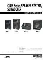
CLUB Series

SPEAKER SYSTEM/

2

SUBWOOFER

IMPOR TANT NOTICE

This manual has been provided for the use of authorized Yamaha Retailers and their service personnel. It has been assumed
that basic service procedures inherent to the industry, and more specifically Yamaha Products, are already known and under-
stood by the users, and have therefore not been restated.

WARNING :

Failure to follow appropriate service and safety procedures when servicing this product may result in per-
sonal injury, destruction of expensive components and failure of the product to perform as specified. For
these reasons, we advise all Yamaha product owners that all service required should be performed by an
authorized Yamaha Retailer or the appointed service representative.

IMPORTANT :

This presentation or sale of this manual to any individual or firm does not constitute authorization certifi-
cation, recognition of any applicable technical capabilities, or establish a principal-agent relationship of
any form.

The data provided is belived to be accurate and applicable to the unit(s) indicated on the cover. The research engineering, and
service departments of Yamaha are continually striving to improve Yamaha products. Modifications are, therefore, inevitable
and changes in specification are subject to change without notice or obligation to retrofit. Should any discrepancy appear to
exist, please contact the distributor’s Service Division.

WARNING :

Static discharges can destroy expensive components. Discharge any static electricity your body may
have accumulated by grounding yourself to the ground buss in the unit  (heavy gauge black wires connect
to  this buss.)

IMPORTANT :

Turn the unit  OFF  during disassembly and parts replacement. Recheck  all  work before you apply power
to the unit.

WARNING: CHEMICAL CONTENT NOTICE!

The solder used in the production of this product contains LEAD. In addition, other electrical/electronic and/or plastic (Where
applicable) components may also contain traces of chemicals found by the California Health and Welfare Agency (and possibly
other entities) to cause cancer and/or birth defects or other reproductive harm.

DO NOT PLACE SOLDER, ELECTRICAL/ELECTRONIC OR PLASTIC COMPONENTS IN YOUR MOUTH FOR ANY REASON WHAT
SO EVER!

Avoid prolonged, unprotected contact between solder and your skin! When soldering, do not inhale solder fumes or expose
eyes to solder/flux vapor!

If you come in contact with solder or components located inside the enclosure of this product, wash your hands before handling
food.

WARNING

Components having special characteristics are marked             and must be replaced with parts having specification equal to those
originally installed.

Summary of Contents for CLUB Series

Page 1: ...1 Printed in Japan 2001 9 HAMAMATSU JAPAN CLUBSeriesSPEAKERSYSTEM SUBWOOFER SW1184S CONTENTS SPECIFICATIONS 3 DIMENSIONS 4 SCHEMATIC DIAGRAMS CIRCUIT BOARDS 5 PARTS LIST PA 011602 This document is printed on chlorine free ECF paper with soy ink SM124S S1154S S1124S ...

Page 2: ...itable and changes in specification are subject to change without notice or obligation to retrofit Should any discrepancy appear to exist please contact the distributor s Service Division WARNING Static discharges can destroy expensive components Discharge any static electricity your body may have accumulated by grounding yourself to the ground buss in the unit heavy gauge black wires connect to t...

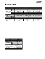
Page 3: ...Hz Input Connectors 1 4 Phone jack x 2 parallel input Dimensions W x H X D 400 x 638 x 318 mm 643 x 402 x 344 mm 475 x 712 x 362 mm Weight 19 3 kg 19 5 kg 27 5 kg Model S1124S SM124S S1154S LF HF NOISE PGM MAX Horizontal Vertical SPECIFICATIONS Enclosure Bass reflex type Speaker Unit 18 cone Frequency Response 30 Hz to 2 kHz Power Capacity 250 W 500 W 1000W Nominal Impedance 8 Ω Sensitivity 96 dB ...

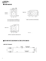
Page 4: ...R SYSTEM 4 SUBWOOFER SCHEMATIC DIAGRAMS CIRCUIT BOARDS S1124S S1154S S1124S WXHXD 400X638X318 S1154S WXHXD 475X712X362 Units mm DIMENSIONS SM124S WXHXD 643X402X344 SM124S SW1184S WXHXD 542X654X791 SW1184S SW1184S Network ...

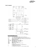
Page 5: ...CLUB Series SPEAKER SYSTEM 5 SUBWOOFER S1154S Network Network NBY06410 Parts List ...

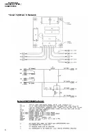
Page 6: ...CLUB Series SPEAKER SYSTEM 6 SUBWOOFER S1124S SM124S Network Network NBY06420 Parts List ...

Page 7: ... are not available as spare parts This mark in the REMARKS column means these parts are interchangeable The second letter of the shaded part number is O not zero The second letter of the shaded part number is I not one M South African model O Chinese model Q South east Asia model T Taiwan model U U S A model V General export model 110V W General export model 220 N X General export model Y Export m...

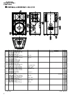
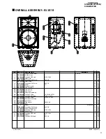
Page 8: ... Pan Head PB Screw 8X1 BLK ZINC 8 27 Input Panel Assembly 27a Input Panel 08 27b Plain Washer 3 8SI SAE 2 01 27c Jack 05 27d Decal CBY0523 29 Truss Head SM Screw 6 X 5 8 6 01 31 Tripod Support MNT35 06 33 Pan Head PB Screw 10 X 1 BLK 3 01 35 Rubber Foot 4 03 37 Pan Head PB Screw 10 X 1 BLK 4 01 45 Network 12 15 47 Pan Head PB Screw 6 X 3 4 4 01 CBY03990 AAY02550 ETAG1030 AAY02200 ETAI1230 JAY51200...

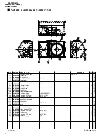
Page 9: ...01 24 Pan Head SM Screw 10 X 1 1 2 BL 25 Pan Head Screw 10 32 X 1 BLK 8 03 27 Input Panel Assembly 27a Input Panel 08 27b Plain Washer 3 8SI SAE 2 01 27c Jack 05 27d Decal CBY0523 29 Truss Head SM Screw 6 X 5 8 6 01 31 Tripod Support MNT35 06 33 Pan Head PB Screw 10 X 1 BLK 3 01 35 Rubber Foot 4 03 37 Pan Head PB Screw 10 X 1 BLK 4 01 45 Network 15 15 47 Pan Head SM Screw 6 X 3 4 4 01 CBY03990 EKY...

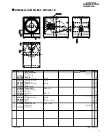
Page 10: ...2 BL 25 Pan Head PB Screw 10 X 1 BLK 7 01 26 Pan Head PB Screw 8X1 BLK ZINC 8 27 Input Panel Assembly 27a Input Panel 08 27b Plain Washer 3 8SI SAE 2 01 27c Jack 05 27d Decal CBY0523 29 Truss Head SM Screw 6 X 5 8 6 01 31 Tripod Support MNT35 06 33 Pan Head PB Screw 10 X 1 BLK 01 35 Rubber Foot 7 03 37 Pan Head PB Screw 10 X 1 BLK 7 01 45 Network 12 15 47 Pan Head SM Screw 6 X 3 4 4 01 AAY02550 CB...

Page 11: ...r Gasket 10 03 25 Pan Head Screw 10 32 X 1 1 2 8 01 27 Input Panel Assembly 27a Input Panel 08 27b Plain Washer 3 8SI SAE 2 01 27c Jack 05 27d Decal CBY0523 29 Truss Head SM Screw 6 X 5 8 6 01 31 Top Hat 1 3 8 14 33 Screw 1 4 20 X 1 1 4 BLK 4 01 35 Rubber Foot 4 02 37 Pan Head PB Screw 10 32 X 1 BLK 4 03 53 Caution Label CBY0339 57 YAMAHA Logo 05 MZY01400 AAY02000 ETAG1030 ETAG1030 AAY02200 ETAI12...

Reviews: