4
1
2
3
5
6
Chapter 3 SYSTEM OVERVIEW
3-11
3.4 SERVICE mode
This section describes SERVICE mode.
3.4.1 What is SERVICE mode?
SERVICE mode is used to perform maintenance work safely using the RPB-E within the
safety fence or enclosure of the robot system.
This mode is enabled only when the controller is set to SAFE mode. The CE marking
compliant controllers are set to SAFE mode at the time when they are shipped.
c
CAUTION
The CE marking compliant controllers are always set to SAFE mode.
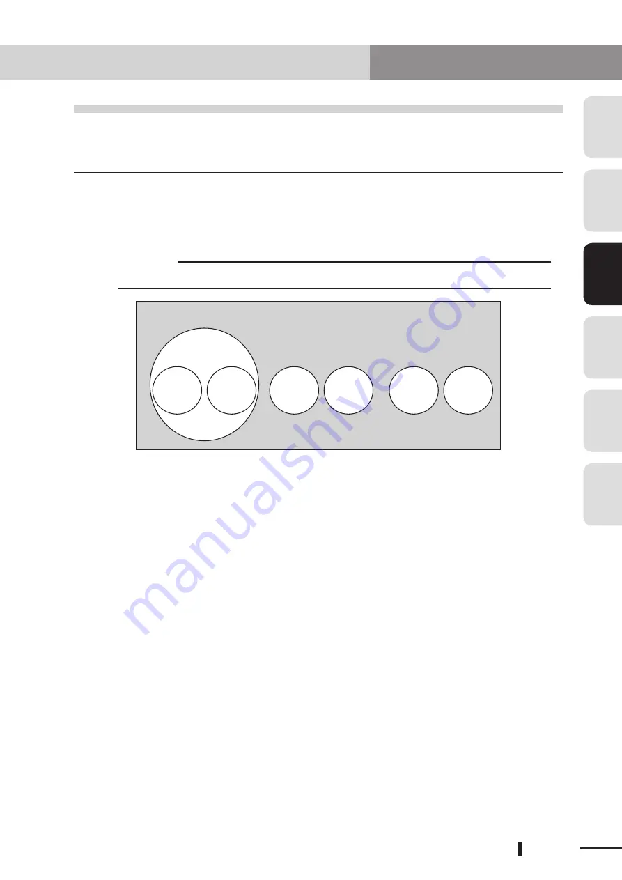
"SERVICE" mode
Basic operation modes
"AUTO"
mode
"MANUAL"
mode
"PROGRAM"
mode
"SYSTEM"
mode
"DI/DO
monitor"
mode
"UTILITY"
mode
SERVICE mode includes AUTO and MANUAL modes in the basic operation mode, and is
selected by opening (turning OFF) the DI02 contact (SERVICE mode input). Normal mode
is maintained as long as the DI02 contact is closed (ON).
If a serial I/O option board is installed, SERVICE mode is entered when either one of SI02
or DI02 is open (OFF). (Normal mode is entered only when both SI02 and DI02 contacts
are closed.)
When the DI02 contact is open (OFF), the controller is in SERVICE mode with the
operation level, operating speed limit, and exclusive control of the operating devices
specified by the SERVICE mode parameters. The following functions can be selected in
SERVICE mode.
1. Robot is controlled only by RPB-E operation.
2. Automatic operation is prohibited.
3. Robot operating speed is set to below 3% of the maximum speed.
4. Robot operation is possible only by hold-to-run control.
(The Hold-to-Run function allows the robot to move (including program execution)
only during the time that the RPB-E operation key is kept pressed.)
In SAFE mode setting, therefore, the operations in AUTO mode and MANUAL mode differ
from those in normal mode, depending on the SERVICE mode parameter settings.
3.4 SERVICE mode
Summary of Contents for CEmarking RCX221
Page 2: ......
Page 4: ...MEMO 2 Introduction ...
Page 8: ...MEMO iv General contents ...
Page 10: ......
Page 22: ......
Page 26: ...MEMO 2 4 Chapter 2 CE MARKING ...
Page 28: ......
Page 44: ......
Page 56: ...4 12 Chapter 4 EMC COUNTERMEASURE MEMO ...
Page 58: ......
Page 72: ...MEMO 5 14 Chapter 5 EXTERNAL SAFETY CIRCUIT EXAMPLES ...
Page 74: ......
Page 91: ...MEMO ...


