CDX-E200
CDX-E200
5
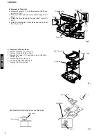
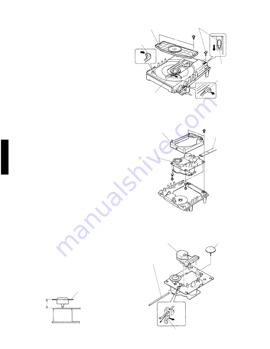
Disc Table
Pick-up Head
Gear A
Sled Shaft
19.4
±
0.2mm
Stopper
Check that the disc table height is as specified below.
Fig. 5
Fig. 3
Fig. 4
Stopper
y
Stopper Pin
u
Sub Chassis (S)
i
i
Chucking Unit
Stopper
Hook
Drive Gear
Drive Unit
5. Removal of Pick-up Head
a. Remove 2 screws (
u
) in Fig. 4.
b. Remove a pick-up cable in Fig. 4.
c. Remove 4 screws (
i
) and then remove the Drive
Unit in Fig. 4.
d. Remove the gear A in Fig. 5.
e. Pull out the Sled Shaft in Fig. 5.
f. Remove the Pick-up Head.
4. Removal of Tray Unit
a. Remove 2 screws (
y
) and then remove the Chuck-
ing Unit in Fig. 3.
b. Remove 1 hook and then remove the Stopper Pin in
Fig. 3.
c. Rotate the Drive Gear and then open the Tray Unit in
Fig. 3.
d. Detach the Stoppers on both sides and then pull out
the Tray in Fig. 3.
Pick-up Cable
Summary of Contents for CDX-E200
Page 33: ...CDX E200 CDX E200 ...


