
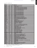


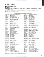
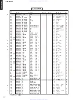


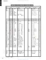


2
A
B
C
D
E
G
H
I
J
1
3
4
5
7
CDR-HD1500
6
50
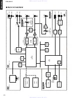
■
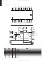
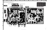
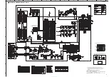
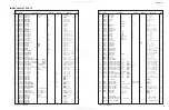
SCHEMATIC DIAGRAM (WCLK)
★
All voltage are measured with a 10M
Ω
/V DC electric volt meter.
★
Components having special characteristics are marked
s
and must be
replaced with parts having specifications equal to those originally
installed.
★
Schematic diagram is subject to change without notice.
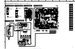
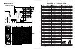
PIN CONNECTION DIAGRAM OF TRANSISTORS,
DIODES AND ICS.
P
age 45
to MAIN
A3
B4
IC801: SN74LV393ANSR
Dual 4-Bit Binary Counters
1
2
3
4
5
6
7
14
13
12
11
10
9
8
1CLK
1CLR
1Q
A
1Q
B
1Q
C
1Q
D
GND
V
CC
2CLK
2CLR
2Q
A
2Q
B
2Q
C
2Q
D
R
T
Q
A
CLR
CLK
R
T
Q
B
R
T
Q
C
R
T
Q
D
Q
Q
Q
Q
SN74LV393ANSR
14
7
1
IC802: TC74HCU04AFEL
Hex Inverters
1A
1Y
2Y
VCC
6A
1
2
3
4
11
2A
6Y
5A
12
13
14
3A
3Y
5Y
4A
5
6
7
4Y
8
9
10
GND
TC74HCU04AFEL
1
7
14
5
9
11
13
1
2
3
4
WCLK
w w w . x i a o y u 1 6 3 . c o m
Q Q 3 7 6 3 1 5 1 5 0
9
9
2
8
9
4
2
9
8
T E L
1 3 9 4 2 2 9 6 5 1 3
9
9
2
8
9
4
2
9
8
0
5
1
5
1
3
6
7
3
Q
Q
TEL 13942296513 QQ 376315150 892498299
TEL 13942296513 QQ 376315150 892498299


