background image

SPECIFICATIONS

8-4

8

EAU01038

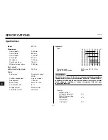
Battery

Model

GT14B-4

Voltage, capacity

12 V, 12 Ah

Headlight type

Quartz bulb (halogen)

Bulb voltage, wattage x quantity

Headlight

12 V 60 W / 55 W x 1

Auxiliary light

12 V 5 W x 1

Tail/brake light

12 V 5 W / 21 W 

Turn signal indicator light

12 V 10 W x 4

Meter lighting

14 V - 1.2 W x 4

Oil level warning light

LED x 1

Neutral indicator light

LED x 1

Turn signal light

LED x 1

High beam indicator light

LED x 1

Fuel level warning light

LED x 1

Fuses

Main fuse

30 A

Backup fuse (odometer)

5 A

Ignition fuse

10 A

Headlight fuse

15 A

Carburetor heater fuse

15 A

Signaling system fuse

10 A

Summary of Contents for Bulldog BT1100

Page 1: ...USO E MANUTENZIONE OWNER S MANUAL MANUEL DU PROPRIÉTAIRE BEDIENUNGSANLEITUNG MANUAL DEL PROPIETARIO 5JN F8199 A0 BT1100 ...

Page 2: ... manual thoroughly so as to enjoy all advantages of your BT1100 The owner s manual does not only instruct you in how to operate inspect and maintain your motorcycle but also in how to safe guard yourself and others from trouble and injury In addition the many tips given in this manual will help keep your motorcycle in the best possible condition If you have any further questions do not hesitate to...

Page 3: ...hat must be taken to avoid damage to the motorcycle NOTE A NOTE provides key information to make procedures easier or clearer WARNING NOTE This manual should be considered a permanent part of this motorcycle and should remain with it even if the motorcycle is subsequently sold Yamaha continually seeks advancements in product design and quality Therefore while this manual contains the most current ...

Page 4: ...IMPORTANT MANUAL INFORMATION EAU00005 EW000002 WARNING0 PLEASE READ THIS MANUAL CAREFULLY AND COMPLETELY BEFORE OPERATING THIS MOTORCYCLE ...

Page 5: ...NER S MANUAL 2001 by Belgarda S p A 1st edition july 2001 All rights reserved Any reprinting or unauthorized use without the written permission of Belgarda S p A is expressly prohibited Printed in Italy EAUBOOOO ...

Page 6: ... WAY DESCRIPTION INSTRUMENT AND CONTROL FUNCTIONS PRE OPERATION CHECKS OPERATION AND IMPORTANT RIDING POINTS PERIODIC MAINTENANCE AND MINOR REPAIR MOTORCYCLE CARE AND STORAGE SPECIFICATIONS CONSUMER INFORMATION INDEX TABLE OF CONTENTS EAU00009 ...

Page 7: ...1 Give safety the right of way 1 1 GIVE SAFETY THE RIGHT OF WAY EAU00021 ...

Page 8: ... best Under the influence of even small amounts of alcohol there is a tendency to take dangerous risks Protective clothing is as essential for the motorcycle rider as seat belts are for car drivers and passengers Always wear a complete motorcycle suit whether made of leather or tear resistant synthetic materials with protectors sturdy boots motorcycle gloves and a properly fitting helmet Optimum p...

Page 9: ...2 Left view 2 1 Right view 2 2 Controls and instruments 2 3 DESCRIPTION EAU00026 ...

Page 10: ...lever page 3 12 2 Storage compartment page 3 14 3 Tool kit page 6 1 4 Spring preload adjusting ring shock absorber assembly page 3 15 5 Shift pedal page 3 10 6 Engine oil level window page 6 6 DESCRIPTION Left view EAU00026 2 1 2 ...

Page 11: ...0 12 11 DESCRIPTION EAU00026 2 2 2 7 Fuse box page 6 28 8 Battery page 6 26 9 Helmet holders page 3 14 10 Air filter element page 6 10 11 Engine oil filter element page 6 6 12 Brake pedal page 3 10 Right view ...

Page 12: ...0026 2 3 2 1 Clutch lever page 3 9 2 Left handlebar switches page 3 8 3 Instruments and warning lights page 3 2 4 Main switch and steering lock page 3 1 5 Right handlebar switches page 3 9 6 Throttle grip page 6 13 7 Front brake lever page 3 10 8 Fuel tank cap page 3 11 Controls and instruments ...

Page 13: ... 3 8 Clutch lever 3 9 Shift pedal 3 10 Brake lever 3 10 Brake pedal 3 10 Fuel tank cap 3 11 Fuel 3 11 Fuel tank breather hose 3 12 Starter choke lever 3 12 Seat 3 13 Helmet holders 3 14 Storage compartment 3 14 Adjusting the front fork 3 15 Adjusting the shock absorber assembly 3 15 Sidestand 3 16 Ignition circuit cut off system 3 17 INSTRUMENT AND CONTROL FUNCTIONS EAU00027 ...

Page 14: ...emoved To lock the steering 1 Turn the handlebars all the way to the left 2 Push the key in from the B OFF po sition and then turn it to D LOCK while still pushing it 3 Remove the key To unlock the steering Push the key in and then turn it to B OFF while still pushing it 1 Push 2 Turn EAU00027 3 1 3 INSTRUMENT AND CONTROL FUNCTIONS EW000016 WARNING0 Never turn the key to B OFF or D LOCK while the ...

Page 15: ...I ON The warn ing light should come on for a few seconds 1 Oil level warning light v 2 Turn signal indicator light y y 3 Neutral indicator light N 4 High beam indicator light 1 5 Fuel level warning light K 2 If the warning light does not come on have a Yamaha dealer check the electrical circuit NOTE Even if the oil level is sufficient the warn ing light may flicker when riding on a slope or during...

Page 16: ...rning light circuit See page 3 6 for an explanation of the self diagnosis device EAUB0003 Speedometer unit The speedometer unit is equipped with the following a speedometer which shows riding speed a tachometer which shows engine r min an odometer which shows the total distance traveled 1 Speedometer set to km h 2 Tachometer 3 Odometer tripmeter fuel reserve tripmeter clock display 4 SET button 5 ...

Page 17: ...one second If you do not reset the fuel reserve tripmeter manually it will reset itself automatically and the display will return to the prior mode after refueling and traveling several kilometers Oil change indicator At the initial 1 000 km 620 mi and every 10 000 km 6 200 mi thereafter the mes sage OIL CHANGE appears in the dis play for a few seconds when the key is turned to ON to indicate that...

Page 18: ...SET button and SET button together for at least two sec onds 3 When the hour digits start flashing push the RESET button to set the hours between 1 and 12 4 Push the SET button and the first of the two minute digits will start flash ing 5 Push the RESET button to set the first minute digit between 0 and 5 6 Push the SET button and the sec ond of the two minute digits will start flashing 7 Push the...

Page 19: ...e 6 400 r min and above CAUTION EAUB0004 Self diagnosis device NOTE When the key is turned to I ON the tachometer and speedometer needles should move to the maximum then back to zero In addition the oil level warning light and fuel level warning light should come on for a few seconds then go off If the tachometer or speedometer needle does not move as described or either of the warning lights does...

Page 20: ...ote the circuit specific number of r min and then have a Yamaha dealer check the motorcycle EC000004 When the tachometer displays an error code the motorcycle should be checked as soon as possible in order to avoid engine damage CAUTION 0 r min for 3 seconds Circuit specific number of r min for 2 5 seconds see the table below Specific Faulty electrical r min circuit 3 000 r min Throttle position s...

Page 21: ...e can be equipped with an optional anti theft alarm by a Yamaha dealer Contact a Yamaha dealer for more information EAU00118 Handlebar switches EAU03889 Turn signal switch y y To signal a right hand turn push this switch to To signal a left hand turn push this switch to Ÿ Ÿ When released the switch returns to the center position To cancel the turn signal lights push the switch in after it has retu...

Page 22: ...witch J Push this switch to crank the engine with the starter EC000005 See page 5 1 for starting instructions prior to starting the engine CAUTION EAU00152 Clutch lever The clutch lever is located at the left han dlebar grip To disengage the clutch pull the lever toward the handlebar grip To en gage the clutch release the lever The lever should be pulled rapidly and re leased slowly for smooth clu...

Page 23: ... lever toward the handlebar grip The brake lever is equipped with a position adjusting dial To adjust the distance be tween the brake lever and the handlebar grip turn the adjusting dial while holding the lever pushed away from the handlebar grip Make sure that the appropriate set ting on the adjusting dial is aligned with the arrow mark on the brake lever EAU00162 Brake pedal The brake pedal is o...

Page 24: ...t and then close the lock cover NOTE The fuel tank cap cannot be closed unless the key is in the lock In addition the key cannot be removed if the cap is not prop erly closed and locked EWA00025 WARNING0 Make sure that the fuel tank cap is properly closed before riding EAU03753 Fuel Make sure that there is sufficient fuel in the tank Fill the fuel tank to the bottom of the filler tube as shown EW0...

Page 25: ...e amount 5 8 L 1 Fuel tank breather hose EAU02955 Fuel tank breather hose Before operating the motorcycle Check the fuel tank breather hose connec tion Check the fuel tank breather hose for cracks or damage and replace it if dam aged Make sure that the end of the fuel tank breather hose is not blocked and clean it if necessary EAU03839 Starter choke lever Starting a cold engine requires a richer a...

Page 26: ...urs turn off the starter choke CAUTION EAU01726 Seat To remove the seat 1 Insert the key into the seat lock and then turn it clockwise 2 Pull the seat off 1 Open 1 Projection 2 Seat holder To install the seat 1 Insert the projections on the front of the seat into the seat holders as shown 2 Push the rear of the seat down to lock it in place 3 Remove the key NOTE Make sure that the seat is properly...

Page 27: ...stall the seat EWA00015 WARNING0 Never ride with a helmet attached to a helmet holder since the helmet may hit objects causing loss of control and possibly an accident EAUB0006 Storage compartment The storage compartment is located under the seat See page 3 13 for seat removal and installation procedures This storage compartment is designed to hold a genuine Yamaha U LOCK Other locks may not fit T...

Page 28: ... in direction a To de crease the spring preload and thereby soften the suspension turn the adjusting bolt on each fork leg in direction b NOTE Align the appropriate groove on the adjust ing mechanism with the top of the front fork cap bolt EAUB0007 Adjusting the shock absorber assembly This shock absorber assembly is equipped with a spring preload adjusting nut EC000015 Never attempt to turn an ad...

Page 29: ...OTE The built in sidestand switch is part of the ignition circuit cut off system which cuts the ignition in certain situations See fur ther down for an explanation of the ignition circuit cut off system 3 16 3 Spring preload Minimum soft Distance A 170 mm Standard Distance A 162 mm Maximum hard Distance A 154 mm Tightening torque Locknut 45 Nm 4 5 m kg EAU00315 WARNING0 This shock absorber contain...

Page 30: ...if it does not function properly EAU03720 Ignition circuit cut off system The ignition circuit cut off system com prising the sidestand switch clutch switch and neutral switch has the following func tions It prevents starting when the trans mission is in gear and the sidestand is up but the clutch lever is not pulled It prevents starting when the trans mission is in gear and the clutch lever is pu...

Page 31: ...d down Does the engine stall The neutral switch may be defective The motorcycle should not be ridden until checked by a Yamaha dealer The sidestand switch may be defective The motorcycle should not be ridden until checked by a Yamaha dealer The clutch switch may be defective The motorcycle should not be ridden until checked by a Yamaha dealer After the engine has stalled 10 Move the sidestand up 1...

Page 32: ...Pre operation check list 4 1 4 PRE OPERATION CHECKS EAU01114 ...

Page 33: ...heck fuel level in fuel tank Fuel Refuel if necessary 3 11 Check fuel line for leakage Check oil level in engine Engine oil If necessary add recommended oil to specified level 6 6 Check vehicle for oil leakage Final gear oil Check vehicle for oil leakage 6 8 Check operation If soft or spongy have Yamaha dealer bleed hydraulic system Front brake Check fluid level in reservoir 3 10 6 19 If necessary...

Page 34: ...pressure 6 13 6 16 Correct if necessary Brake and shift Make sure that operation is smooth pedals Lubricate pedal pivoting points if necessary 6 23 Brake and clutch Make sure that operation is smooth levers Lubricate lever pivoting points if necessary 6 23 Make sure that operation is smooth Sidestand Lubricate pivot if necessary 6 24 Chassis Make sure that all nuts bolts and screws are properly ti...

Page 35: ...d Such an inspection can be accomplished in a very short time and the added safety it assures is more than worth the time involved EWA00033 WARNING0 If any item in the Pre operation check list is not working properly have it inspected and repaired before operating the motor cycle EAU01114 4 3 4 ...

Page 36: ...5 Starting the engine 5 1 Starting a warm engine 5 3 Shifting 5 3 Tips for reducing fuel consumption 5 4 Engine break in 5 4 Parking 5 5 OPERATION AND IMPORTANT RIDING POINTS EAU00372 ...

Page 37: ...ition circuit cut off sys tem to enable starting one of the following conditions must be met The transmission is in the neutral po sition The transmission is in gear with the clutch lever pulled and the sidestand up EW000054 WARNING0 Before starting the engine check the function of the ignition circuit cut off system according to the procedure described on page 3 18 Never ride with the sidestand d...

Page 38: ...essary add engine oil and then check the warning light again If the warning light does not come on when pushing the start switch or if it does not go off after starting with suffi cient engine oil have a Yamaha dealer check the electrical circuit If the fuel level warning light remains on after starting stop the engine and then check the fuel level If necessary refuel as soon as possible and then ...

Page 39: ...to the neutral position press the shift pedal down repeatedly until it reaches the end of its travel and then slightly raise it EC000048 Even with the transmission in the neutral position do not coast for long periods of time with the engine off and do not tow the motorcycle for long distances The transmission is properly lubricat ed only when the engine is run ning Inadequate lubrication may dama...

Page 40: ... 1 600 km 1 000 mi For this reason you should read the following ma terial carefully Since the engine is brand new do not put an excessive load on it for the first 1 600 km 1 000 mi The various parts in the en gine wear and polish themselves to the correct operating clearances During this period prolonged full throttle operation or any condition that might result in engine overheating must be avoi...

Page 41: ...d then remove the key from the main switch EW000058 WARNING0 Since the engine and exhaust sys tem can become very hot park in a place where pedestrians or chil dren are not likely to touch them Do not park on a slope or on soft ground otherwise the motorcycle may overturn 5 5 5 EAU00372 ...

Page 42: ... 19 Changing the brake fluid 6 21 Adjusting the shift pedal position 6 21 Checking and lubricating the cables 6 22 Checking and lubricating the throttle grip and cable 6 22 Checking and lubricating the brake and shift pedals 6 23 Checking and lubricating the brake and clutch levers 6 23 Checking and lubricating the sidestand 6 24 Checking the front fork 6 24 Checking the steering 6 25 Checking the...

Page 43: ...amiliar with motorcycle maintenance work have a Yamaha dealer do it for you 1 Owner s tool kit EAU01129 Owner s tool kit The owner s tool kit is located inside the storage compartment see page 3 13 for storage compartment opening proce dures The service information included in this manual and the tools provided in the own er s tool kit are intended to assist you in the performance of preventive ma...

Page 44: ...aler as they require special tools data and technical skills 6 2 6 ODOMETER READING x 1 000 km ANNUAL N0 ITEM CHECK OR MAINTENANCE JOB 1 10 20 30 40 CHECK 1 Fuel line Check fuel hoses and vacuum hose for cracks or damage 2 Fuel filter Check condition Check condition 3 Spurk plugs Clean and regap Replace 4 Valves Check valve clearance Adjust 5 Air filter element Clean Replace 6 Clutch Check operati...

Page 45: ...essary 12 Wheel bearings Check bearing for looseness or damage 13 Swingarm Check operation and for excessive play Lubrificate with lithium soap based grease Every 50 000 km 14 Steering bearings Check bearing play and steering for roughness Lubrificate with lithium soap based grease Every 20 000 km 15 Chassis fasteners Make sure that all nuts bolts and screws are properly tightened 16 Sidestand Che...

Page 46: ...ING x 1 000 km ANNUAL N0 ITEM CHECK OR MAINTENANCE JOB 1 10 20 30 40 CHECK Rear suspension Check operation 20 relay arm and connecting arm Lubricate with lithium soap based grease pivoting points Check starter choke operation 21 Carburators Adjust engine idling speed and synchronization 22 Engine oil Change 23 Engine oil filter Replace element Check oil level and vehicle for oil 24 Final gear leak...

Page 47: ...aintenance and lubrication chart In addition the condition of the spark plugs can reveal the condition of the engine EAU01122 Removing and installing panels The panels shown above need to be re moved to perform some of the mainte nance jobs described in this chapter Refer to this section each time a panel needs to be removed and installed EAU00488 Panel To remove the panel Remove the screw and the...

Page 48: ... soon as possible 4 Install the spark plug cap 5 Place the spark plug cover in the orig inal position 6 6 6 a Spark plug gap To check the spark plugs 1 Check that the porcelain insulator around the center electrode on each spark plug is a medium to light tan the ideal color when the motorcycle is ridden normally 2 Check that all spark plugs installed in the engine have the same color NOTE If any s...

Page 49: ... oil of the recommended type to raise it to the correct level To change the engine oil without oil filter element replacement 1 Start the engine warm it up for sever al minutes and then turn it off 2 Place an oil pan under the engine to collect the used oil 3 Remove the engine oil filler cap and drain bolt to drain the oil from the crankcase 6 7 6 2 3 1 EAU01712 Engine oil and oil filter element T...

Page 50: ...light should go off if the oil level is sufficient EC000067 If the oil level warning light flickers or remains on immediately turn the engine off and have a Yamaha dealer check the vehicle 7 Turn the engine off and then check the oil level and correct it if neces sary NOTE Have a Yamaha dealer replace the oil filter element when necessary CAUTION 1 Engine oil drain bolt 6 8 6 1 4 Install the engin...

Page 51: ...l of the recom mended type to raise it to the correct level To change the final gear oil 1 Place an oil pan under the final gear case to collect the used oil 2 Remove the oil filler bolt and drain bolt to drain the oil from the final gear case 6 9 6 1 Final gear oil drain bolt 2 Final gear oil filler bolt 3 Oil level EAU04083 Final gear oil The final gear case must be checked for oil leakage befor...

Page 52: ...E GL4 is a quality rating Hypoid gear oils rated GL5 or GL6 may also be used 5 Install and tighten the oil filler bolt 1 Remove the seat See page 3 13 for seat removal and installation proce dures 2 Remove panels 1 and 2 See page 6 5 for panel removal and installation procedures 3 Remove the fuel tank bolts 6 10 6 Tightening torque Final gear oil drain bolt 23 Nm 2 3 m kgf Recommended final gear o...

Page 53: ...over 3 Air filter ECA00089 The engine should never be operated without the air filter element installed otherwise the piston s and or cylin der s may become excessively worn 9 Install the air filter case cover by in stalling the screws 10 Install the fuel tank by installing the bolts 11 Install the panels CAUTION EAU00462 6 11 6 4 Lift the fuel tank to position it away from the air filter case Do ...

Page 54: ...peed The engine idling speed must be checked and if necessary adjusted as follows at the intervals specified in the periodic main tenance and lubrication chart NOTE A diagnostic tachometer is needed to make this adjustment 1 Attach the tachometer to the spark plug lead 2 Start the engine and warm it up for several minutes at 1 000 2 000 r min while occasionally revving it to 4 000 5 000 r min NOTE...

Page 55: ...t this from occur ring the valve clearance must be adjusted by a Yamaha dealer at the intervals speci fied in the periodic maintenance and lubri cation chart 6 13 6 a Throttle cable free play 1 b a 3 Check the engine idling speed and if necessary adjust it to specification by turning the throttle stop screw To in crease the engine idling speed turn the screw in direction a To decrease the engine i...

Page 56: ... with regard to the load Check the tire condition and air pressure before each ride 6 14 6 EAU00658 Tires To maximize the performance durability and safe operation of your motorcycle note the following points regarding the specified tires Tire air pressure The tire air pressure should be checked and if necessary adjusted before each ride EW000082 WARNING0 The tire air pressure must be checked and ...

Page 57: ...s with valves EW000080 WARNING0 The front and rear tires should be of the same make and design oth erwise the handling characteris tics of the motorcycle cannot be guaranteed After extensive tests only the tires listed below have been approved for this model by Yamaha Motor Co Ltd Always make sure that the valve caps are securely installed to pre vent air pressure leakage Use only the tire valves ...

Page 58: ...essure according to the operating condi tions EAU03773 Cast wheels To maximize the performance durability and safe operation of your motorcycle note the following points regarding the specified wheels The wheel rims should be checked for cracks bends or warpage before each ride If any damage is found have a Yama ha dealer replace the wheel Do not at tempt even the smallest repair to the wheel A de...

Page 59: ...free play should measure 5 10 mm as shown Periodically check the clutch lever free play and if necessary ad just it as follows 1 Loosen the locknut at the clutch lever 2 To increase the clutch lever free play turn the adjusting bolt in direction a To decrease the clutch lever free play turn the adjusting bolt in direction b 3 Tighten the locknut NOTE If the specified free play cannot be obtained a...

Page 60: ...and if nec essary have a Yamaha dealer adjust it EW000109 WARNING0 A soft or spongy feeling in the brake pedal can indicate the presence of air in the hydraulic system If there is air in the hydraulic system have a Yamaha dealer bleed the system before operat ing the motorcycle Air in the hydraulic system will diminish the braking per formance which may result in loss of control and an accident a ...

Page 61: ...he brake If a brake pad has worn to the point that the wear indicator almost touches the brake disc have a Yamaha dealer replace the brake pads as a set EAU03776 Checking the brake fluid level Insufficient brake fluid may allow air to en ter the brake system possibly causing it to become ineffective Before riding check that the brake fluid is above the minimum level mark and replen ish if necessar...

Page 62: ...oor braking performance Be careful that water does not enter the brake fluid reservoir when refill ing Water will significantly lower the boiling point of the fluid and may re sult in vapor lock Brake fluid may deteriorate painted surfaces or plastic parts Always clean up spilled fluid immediately As the brake pads wear it is normal for the brake fluid level to gradually go down However if the bra...

Page 63: ... calipers as well as the brake hoses replaced at the in tervals listed below or whenever they are damaged or leaking Oil seals Replace every two years Brake hoses Replace every four years a Distance between shift pedal and footrest EAUB0011 Adjusting the shift pedal position The top of the shift pedal should be posi tioned approximately 45 mm below the top of the footrest as shown Periodically che...

Page 64: ...p and the condition of the throttle cable should be checked before each ride and the cable should be lubricated or replaced if neces sary NOTE Since the throttle grip must be removed to access the throttle cable end the throttle grip and the cable should always be lubri cated at the same time 1 Remove the throttle grip by removing the screws 2 Disconnect the throttle cable hold it up and then appl...

Page 65: ...al pivots should be lubricated if necessary EAU03164 Checking and lubricating the brake and clutch levers The operation of the brake and clutch levers should be checked before each ride and the lever pivots should be lubri cated if necessary EAU00462 6 23 6 Recommended lubricant Lithium soap based grease all purpose grease Recommended lubricant Lithium soap based grease all purpose grease ...

Page 66: ...d hold it in an upright position 2 While applying the front brake push down hard on the handlebars several times to check if the front fork com presses and rebounds smoothly EC000098 If any damage is found or the front fork does not operate smoothly have a Yamaha dealer check or repair it CAUTION 6 24 6 EAU03165 Checking and lubricating the sidestand The operation of the sidestand should be checke...

Page 67: ...000115 WARNING0 Securely support the motorcycle so that there is no danger of it falling over 2 Hold the lower ends of the front fork legs and try to move them forward and backward If any free play can be felt have a Yamaha dealer check or repair the steering EAU01144 Checking the wheel bearings The front and rear wheel bearings must be checked at the intervals specified in the periodic maintenanc...

Page 68: ...in eyes or clothing and always shield your eyes when working near batteries In case of contact administer the following FIRST AID CAUTION EXTERNAL Flush with plenty of water INTERNAL Drink large quanti ties of water or milk and imme diately call a physician EYES Flush with water for 15 minutes and seek prompt med ical attention Batteries produce explosive hydrogen gas Therefore keep sparks flames ...

Page 69: ... 2 If the battery will be stored for more than two months check it at least once a month and fully charge it if necessary 3 Fully charge the battery before instal lation 4 After installation make sure that the battery leads are properly connected to the battery terminals EC000102 Always keep the battery charged Storing a discharged battery can cause permanent battery damage To charge a sealed type...

Page 70: ... use a fuse of a higher amperage rating than recommended to avoid causing extensive damage to the elec trical system and possibly a fire 3 Turn the key to I ON and turn on the electrical circuit in question to check if the device operates 4 If the fuse immediately blows again have a Yamaha dealer check the electrical system CAUTION 1 Fuse box cover 2 Main fuse 3 Headlight fuse 4 Signaling system f...

Page 71: ...ove the headlight by removing the screws then tilt the cowling for ward 2 Disconnect the headlight coupler and the auxiliary light leads and then re move the headlight bulb cover 3 Remove the headlight bulb holder by turning it counterclockwise and then remove the defective bulb EW000119 WARNING0 Headlight bulbs get very hot There fore keep flammable products away from a lit headlight bulb and do ...

Page 72: ...ect the coupler and auxil iary light leads 6 Remove the socket together with the bulb by turning it counterclockwise 7 Remove the defective bulb by push ing it in and turning it counterclock wise 8 Insert a new bulb into the socket push it in and then turn it clockwise until it stops 9 Install the socket together with the bulb by turning it clockwise 10 Connect the auxiliary light bulb leads 11 Ti...

Page 73: ... in and turning it counterclock wise 3 Insert a new bulb into the socket push it in and then turn it clockwise until it stops 4 Install the lens by installing the screw EC000065 Do not overtighten the screw other wise the lens may break CAUTION EAU01623 Replacing the tail brake light bulb 1 Remove the tail brake light lens by re moving the screws 2 Remove the defective bulb by push ing it in and t...

Page 74: ...6 Install the license plate light by in stalling the nuts EAUB0015 Front wheel To remove the front wheel EW000122 WARNING0 It is advisable to have a Yamaha dealer service the wheel Securely support the motorcycle so that there is no danger of it falling over 1 Mark either side of the wheel so that it can be installed in the original running direction 2 Remove the brake calipers by remov ing the bo...

Page 75: ...the front wheel axle pinch bolt and the brake caliper bolts to the specified torques EAUB0017 Rear wheel To remove the rear wheel EW000122 WARNING0 It is advisable to have a Yamaha dealer service the wheel Securely support the motorcycle so that there is no danger of it falling over 1 Loosen the rear wheel axle pinch bolt and then remove the axle nut 6 33 6 6 Push down hard on the handlebar severa...

Page 76: ...d grease to the splines of the fi nal gear case and wheel hub 2 Install the wheel by inserting the wheel axle then installing the axle nut 3 Turn the caliper down so that it fits over the brake disc NOTE Make sure that there is enough space between the brake pads before installing the brake caliper onto the brake disc 4 Install the wheel axle pinch bolt 5 Install the brake torque rod bolt at the b...

Page 77: ...of power The following troubleshooting chart repre sents a quick and easy procedure for checking these vital systems yourself However should your motorcycle require any repair take it to a Yamaha dealer whose skilled technicians have the neces sary tools experience and know how to service the motorcycle properly Use only genuine Yamaha replacement parts Imitation parts may look like Yama ha parts ...

Page 78: ...tion Have a Yamaha dealer check the vehicle Wipe off with a dry cloth and correct the spark plug gaps or replace the spark plugs Open the throttle halfway and operate the electric starter Have a Yamaha dealer check the vehicle The engine does not start Check the battery The engine turns over slowly Have a Yamaha dealer check the vehicle There is no compres sion Wet Dry The engine turns over quickl...

Page 79: ...7 Care 7 1 Storage 7 4 MOTORCYCLE CARE AND STORAGE EAU03412 ...

Page 80: ...overs as well as all electrical couplers and con nectors including the spark plug caps are tightly installed 3 Remove extremely stubborn dirt like oil burnt onto the crankcase with a degreasing agent and a brush but never apply such products onto seals gaskets and wheel axles Al ways rinse the dirt and degreaser off with water Cleaning ECA00010 Avoid using strong acidic wheel cleaners especially o...

Page 81: ...ks If the wind shield is scratched use a quality plastic polishing compound after washing After normal use Remove dirt with warm water a mild deter gent and a soft clean sponge and then rinse thoroughly with clean water Use a toothbrush or bottlebrush for hard to reach areas Stubborn dirt and insects will come off more easily if the area is covered with a wet cloth for a few minutes before clean i...

Page 82: ...c 6 Wax all painted surfaces 7 Let the motorcycle dry completely be fore storing or covering it EWA00031 WARNING0 Make sure that there is no oil or wax on the brakes or tires If necessary clean the brake discs and brake linings with a regular brake disc cleaner or acetone and wash the tires with warm water and a mild detergent Before riding at higher speeds test the motorcy cle s braking performan...

Page 83: ...his will prevent fuel deposits from building up Pour the drained fuel into the fuel tank 4 Fill up the fuel tank and add fuel sta bilizer if available to prevent the fuel tank from rusting and the fuel from deteriorating 5 Perform the following steps to protect the cylinders piston rings etc from corrosion a Remove the spark plug caps and spark plugs b Pour a teaspoonful of engine oil into each sp...

Page 84: ...wheels a little every month in order to prevent the tires from becoming de graded in one spot 8 Cover the muffler outlets with plastic bags to prevent moisture from enter ing them 9 Remove the battery and fully charge it Store it in a cool dry place and charge it once a month Do not store the battery in an excessively cold or warm place less than 0 C or more than 30 C For more information on stori...

Page 85: ...8 Specifications 8 1 SPECIFICATIONS EAU01038 ...

Page 86: ...arting system Electric starter Lubrication system Wet sump Engine oil Type Recommended API Service SE SF SG or engine oil classification higher Be sure to use motor oils that do not contain anti friction modifiers Passenger car motor oils often labeled ENERGY CONSERVING II contain anti friction additives which will cause clutch and or starter clutch slippage resulting in reduced component life and...

Page 87: ... mm Clutch type Wet multiple disc Transmission Primary reduction system Spur gear Primary reduction ratio 1 660 Secondary reduction system Shaft drive Secondary reduction ratio 2 875 Transmission type Constant mesh 5 speed Operation Left foot Gear ratio 1st 2 353 2nd 1 667 3rd 1 286 4th 1 032 5th 0 853 Chassis Frame type Twin tube Backbone Caster angle 25 Trail 106 mm Tires Front Type Tubeless Siz...

Page 88: ... MT 3 50 Rear Type Cast wheel Size 17 x MT 5 50 Brakes Front Type Dual disc brake Operation Right hand Fluid DOT 4 Rear Type Single disc brake Operation Right foot Fluid DOT 4 Suspension Front Telescopic fork Rear Swingarm link suspension Spring shock absorber Front Coil spring oil damper Rear Coil spring gas oil damper spring preload adjustable Wheel travel Front 130 mm Rear 113 mm Electrical sys...

Page 89: ...x 1 Tail brake light 12 V 5 W 21 W Turn signal indicator light 12 V 10 W x 4 Meter lighting 14 V 1 2 W x 4 Oil level warning light LED x 1 Neutral indicator light LED x 1 Turn signal light LED x 1 High beam indicator light LED x 1 Fuel level warning light LED x 1 Fuses Main fuse 30 A Backup fuse odometer 5 A Ignition fuse 10 A Headlight fuse 15 A Carburetor heater fuse 15 A Signaling system fuse 1...

Page 90: ... table METRIC TO IMPERIAL Metric unit Multiplier Imperial unit m kg 7 233 ft lb Torque m kg 86 794 in lb cm kg 0 0723 ft lb cm kg 0 8679 in lb Weight kg 2 205 lb g 0 03527 oz Speed km h 0 6214 mi h km 0 6214 mi m 3 281 ft Distance m 1 094 yd cm 0 3937 in mm 0 03937 in cc cm3 0 03527 oz IMP liq Volume cc cm3 0 06102 cu in Capacity L liter 0 8799 qt IMP liq L liter 0 2199 gal IMP liq kg mm 55 997 lb...

Page 91: ...9 Identification numbers 9 1 Key identification number 9 1 Vehicle identification number 9 1 Model label 9 2 CONSUMER INFORMATION EAU01039 ...

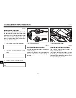
Page 92: ...2 VEHICLE IDENTIFICATION NUM BER 3 MODEL LABEL INFORMATION EAU01041 Key identification number The key identification number is stamped into the key tag Record this number in the space provided and use it for reference when ordering a new key EAU01044 Vehicle identification number The vehicle identification number is stamped into the frame The vehicle identification number is used to identify your ...

Page 93: ...model label is affixed to the frame un der the seat See page 3 13 for seat re moval and installation procedures Record the information on this label in the space provided This information will be needed when ordering spare parts from a Yamaha dealer 9 2 9 EAU01039 ...

Page 94: ...il and oil filter element 6 7 Engine stop switch 3 9 F Final gear oil 6 9 Front fork Adjusting 3 15 Checking 6 24 Front wheel Installing 6 33 Removing 6 32 Fuel 3 11 Fuel consumption tips for reducing 5 4 Fuel level warning light 3 3 Fuel tank breather hose 3 12 Fuel tank cap 3 11 Fuses replacing 6 28 H Handlebar switches 3 8 Headlight bulb replacing 6 29 Helmet holders 3 14 High beam indicator li...

Page 95: ...ometer unit 3 3 Starter choke lever 3 12 Starting a cold engine 5 1 Starting a warm engine 5 3 Start switch 3 9 Steering checking 6 25 Steering lock 3 1 Storage 7 4 Storage compartment 3 14 T Tachometer 3 6 Tail brake light bulb replacing 6 31 Throttle cable free play adjusting 6 13 Throttle grip and cable checking and lubricating 6 22 Tires 6 14 Air pressure 6 14 Tool kit 6 1 Troubleshooting 6 35...

Page 96: ...PRINTED IN ITALY distributrice esclusiva per l Italia 20050 Gerno di Lesmo MI Via Tinelli 67 69 Telefono 039 60961 Ricerca automatica s p a ...

Reviews: