background image

SPEAKER SYSTEM/SUBWOOFER

3

A10/A12/A12M/A15/A15W

REF NO.

PART NO.

DESCRIPTION

REMARKS

QTY

RANK

RANK: Japan only

: New Parts

*
*

*
*
*
*
*
*

*
*

*

*
*

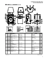
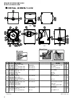
OVERALL ASSEMBLY

A12

2

Speaker

8ohms 200W

12" WOOFER

5

+Bind Head Tapping Screw

D4.0/L16 Black

for HANDLE

10

6

+Bind Head Tapping Screw

D5.0/L20 Black

for 12" WOOFER

8

01

9

Cushion

11

Speaker

8ohms 150W

TWEETER

15

12

+Bind Head Tapping Screw

D4.0/L25 Black

for TW,TERMINAL

10

13

Cushion

110LX14WX1.0T

2

14

Cushion

265LX14WX1.0T

2

16

Metal Grille

20

YAMAHA Logo

BADGE

21

Cushion

for LOGO

22

Push Nut

SPN-4

2

01

23

+Cup Screw

D4.0/L16 Black

for METAL GRILLE

8

01

24

Metal Handle

05

25

Tripod Support Mount

26

+Flat Head Tapping Screw

D5.0/L25 Black

for TSM

4

29

Network

33

+Bind Head Tapping Screw

D3.0/L20 Black

for NETWORK CROSSOVER

4

34

Phone Jack

06

35

Neutrik NL4MP

SPEAKON

06

36

Terminal Plate

2 HOLES,    without LABEL

38

Nut

for NEUTRIK

2

01

39

+Flat Head Machine Screw

M3.0/L12 Black

for NEUTRIK

2

01

40

Rubber Foot

4

42

+Bind Head Wood Screw

D5.0/L30

for RUBBER FOOT

4

43

Polyswitch

RXE050

03

AAX58860
AAX59650
VB857600
WA752200
JAY21400
AAX59670
AAX59680
AAX59690
AAX59710
AAX59750
AAX59760
V 6 2 9 0 0 0 0
WA764400
WA748900
WD887400
AAX59770
AAX59800
V I 0 6 4 7 0 0
WA753900
LAY00180
AAX59840
ES200030
V 5 9 9 3 4 0 0
AAX59860
AAX59870
VV216100

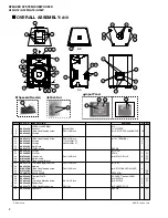
OVERALL ASSEMBLY

: A12

A

A

B

B

B-B

A-A

5

24

5

16

16

25

26

40

42

26

40

42

29

33

13 14

16

23

23

23

2

12

12

6

6

9

20

43

35

39

12

36

34

12

11

23

23

23

21

22

Push Nut

Input Panel

39

35

34

38

11

Speaker(Tweeter)

Summary of Contents for A10

Page 1: ...NUAL PA 011750 Copyright c Yamaha Corporation All rights reserved PDF K103 04 11 HAMAMATSU JAPAN CONTENTS SPECIFICATIONS DIMENSIONS 3 NEUTRIK NL4FC PLUG WIRING 3 CROSSOVER 4 DISASSEMBLY PROCEDURE 9 A10 A12 A15 9 A12M 12 A15W 15 PARTS LIST A10 A12 A15 A12M A15W ...

Page 2: ...rge any static electricity your body may have accumulated by grounding yourself to the ground bus in the unit heavy gauge black wires connect to this bus IMPORTANT Turn the unit OFF during disassembly and parts replacement Recheck all work before you apply power to the unit WARNING CHEMICAL CONTENT NOTICE The solder used in the production of this product contains LEAD In addition other electrical ...

Page 3: ...SPL 1 W 1 m 97 dB SPL 1 W 1 m 97 dB SPL 1 W 1 m Input Connectors 1 4 phone jack x 1 Neutrik SPEAKON NL4MP x 1 1 4 phone jack x 2 Neutrik SPEAKON NL4MP x 2 Socket Mount Diameter 35 mm 1 3 8 Dimensions WxHxD 385 mm x 542 mm x 307 mm 405 mm x 582 mm x 323 mm 470 mmx 672 mm x 375 mm 582 mm x 405 mm x 323 mm 485 mm x 622 mm x 485 mm Weight 13 0 kg 15 5 kg 21 5 kg 15 5 kg 28 0 kg H W D 77 5 102 5 H W D ...

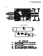
Page 4: ...4 SPEAKER SYSTEM SUBWOOFER A10 A12 A12M A15 A15W CROSSOVER A10 ...

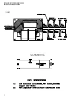
Page 5: ...5 SPEAKER SYSTEM SUBWOOFER A10 A12 A12M A15 A15W A12 ...

Page 6: ...6 SPEAKER SYSTEM SUBWOOFER A10 A12 A12M A15 A15W A12M ...

Page 7: ...7 SPEAKER SYSTEM SUBWOOFER A10 A12 A12M A15 A15W A15 Reversing ...

Page 8: ...8 SPEAKER SYSTEM SUBWOOFER A10 A12 A12M A15 A15W A15W ...

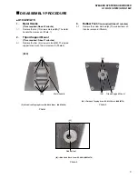
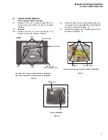
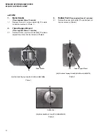
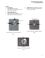
Page 9: ...5 Black AAX59770 42 Rubber foot DISASSEMBLY PROCEDURE A10 A12 A15 1 Metal Handle Time required About 2 minute 1 1 Remove the ten 10 screws marked 5A The metal handle then removed Photo 1 2 Tripod Support Mount Time required About 1 minutes 2 1 Remove the four 4 screws marked 26 The tripod support mount can then be removed Photo 2 3 Rubber Foot Time required About 1 minutes 3 1 Remove the screw mar...

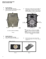
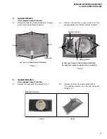
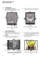
Page 10: ...lack AAX59650 12 Bind Head Tapping Screw D4 0 L25 Black AAX59670 A12 A15 6 Bind Head Tapping ScrewD5 0 L20 Black VB857600 12 Bind Head Tapping Screw D4 0 L25 Black AAX59670 Speaker Tweeter Photo 6 Photo 7 4 2 A10 Remove the eight 8 screws marked 5B The speaker woofer can then be removed Photo 5 A12 A15 Remove the eight 8 screws marked 6 The speaker woofer can then be removed Photo 5 A10 5 Speaker ...

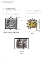
Page 11: ...oved Photo 8 6 2 Network 6 2 1 Remove the four 4 screws marked 33 The network can then be removed Photo 9 12 Bind Head Tapping Screw D4 0 L25 Black AAX59670 39 Flat Head Machine Screw M3 0 L12 Black V5993400 33 Network Terminal Plate 38 Phone Jack 6 3 Remove the two 2 screws marked 39 and the two 2 hexagonal nuts marked 38 The neutrik NL4MP can then be removed Photo 8 10 6 4 Remove the hexagonal n...

Page 12: ...ve the four 4 screws marked 26 The tripod support mount can then be removed Photo 2 Photo 1 5 Bind Head Tapping Screw D4 0 L16 Black AAX59650 Photo 3 Photo 2 42 Bind Head Wood Screw D5 0 L30 AAX59870 26 Flat Head Tapping Screw D5 0 L25 Black AAX59770 5 5 Metal handle 26 26 Tripod Support Mount 42 Rubber foot 3 Rubber Foot Time required About 1 minutes 3 1 Remove the screw marked 42 The rubber foot...

Page 13: ...ping Screw D5 0 L20 Black VB857600 12 Bind Head Tapping Screw D4 0 L25 Black AAX59670 Speaker Tweeter Photo 6 Photo 7 5 Speaker Tweeter Time required About 3 minutes 5 1 Remove the metal grille See procedure 4 1 23 Cup Screw D4 0 L16 Black WA764400 23 23 23 23 Metal grille 4 2 Remove the eight 8 screws marked 6 The speaker woofer can then be removed Photo 5 5 2 Remove the the six 6 screws marked 1...

Page 14: ...e network can then be removed Photo 9 12 Bind Head Tapping Screw D4 0 L25 Black AAX59670 39 Flat Head Machine Screw M3 0 L12 Black V5993400 Terminal Plate Neutrik NL4MP With Hexagonal nut 12B 39 12B Phone Jack 38 Phone Jack 33 Network Terminal Plate 6 3 Remove the two 2 screws marked 39 and the two 2 hexagonal nuts marked 38 The neutrik NL4MP can then be removed Photo 8 10 6 4 Remove the hexagonal...

Page 15: ...Remove the four 4 screws marked 27 The tripod support mount can then be removed Photo 2 Photo 1 5 Bind Head Tapping Screw D4 0 L16 Black AAX59650 Photo 3 Photo 2 42 Bind Head Wood Screw D5 0 L30 AAX59870 5 5 5 Metal handle 27 27 Tripod Support Mount 42 Rubber foot 27 Flat Head Machine Screw M5 0 L40 Black AAX59780 3 Rubber Foot Time required About 1 minutes 3 1 Remove the screw marked 42 The rubbe...

Page 16: ...oto 6 5 2 Network 5 2 1 Remove the four 4 screws marked 33 The network can then be removed Photo 7 Photo 5 4 2 Remove the eight 8 screws marked 7 The speaker woofer can then be removed Photo 5 5 3 Remove the two 2 screws marked 39 and the two 2 hexagonal nuts marked 38 The neutrik NL4MP can then be removed Photo 6 8 5 4 Remove the hexagonal nut The phone jack can then be removed Photo 6 8 Photo 7 ...

Page 17: ...17 SPEAKER SYSTEM SUBWOOFER A10 A12 A12M A15 A15W 18 Nut ES200030 Photo 8 38 38 Phone Jack ...

Page 18: ...o The second letter of the shaded part number is I not one M South African model O Chinese model Q South east Asia model T Taiwan model U U S A model V General export model 110V W General export model 220V N X General export model Y Export model A Australian model B British model C Canadian model D German model E European model F French model H North European model I Indonesian model J Japanese mo...

Page 19: ... 26 Flat Head Tapping Screw D5 0 L25 Black for TSM 4 28 Network 33 Bind Head Tapping Screw D3 0 L20 Black for NETWORK CROSSOVER 4 34 Phone Jack 06 35 Neutrik NL4MP SPEAKON 06 36 Terminal PLATE 2 HOLES without LABEL 38 Nut for NEUTRIK 2 01 39 Flat Head Machine Screw M3 0 L12 Black for NEUTRIK 2 01 40 Rubber Foot 4 42 Bind Head Wood Screw D5 0 L30 for RUBBER FOOT 4 43 Polyswitch RXE050 03 AAX58850 A...

Page 20: ...Flat Head Tapping Screw D5 0 L25 Black for TSM 4 29 Network 33 Bind Head Tapping Screw D3 0 L20 Black for NETWORK CROSSOVER 4 34 Phone Jack 06 35 Neutrik NL4MP SPEAKON 06 36 Terminal Plate 2 HOLES without LABEL 38 Nut for NEUTRIK 2 01 39 Flat Head Machine Screw M3 0 L12 Black for NEUTRIK 2 01 40 Rubber Foot 4 42 Bind Head Wood Screw D5 0 L30 for RUBBER FOOT 4 43 Polyswitch RXE050 03 AAX58860 AAX59...

Page 21: ...d Tapping Screw D5 0 L25 Black for TSM 4 30 Network 33 Bind Head Tapping Screw D3 0 L20 Black for NETWORK CROSSOVER 4 34 Phone Jack 06 35 Neutrik NL4MP SPEAKON 06 36 Terminal Plate 2 HOLES without LABEL 38 Nut for NEUTRIK 2 01 39 Flat Head Machine Screw M3 0 L12 Black for NEUTRIK 2 01 40 Rubber Foot 7 42 Bind Head Wood Screw D5 0 L30 for RUBBER FOOT 7 43 Polyswitch RXE050 03 AAX58860 AAX59650 VB85...

Page 22: ... Flat Head Tapping Screw D5 0 L25 Black for TSM 4 31 Network 33 Bind Head Tapping Screw D3 0 L20 Black for NETWORK CROSSOVER 4 34 Phone Jack 06 35 Neutrik NL4MP SPEAKON 06 36 Terminal Plate 2 HOLES without LABEL 38 Nut for NEUTRIK 2 01 39 Flat Head Machine Screw M3 0 L12 Black for NEUTRIK 2 01 40 Rubber Foot 4 42 Bind Head Wood Screw D5 0 L30 for RUBBER FOOT 4 43 Polyswitch RXE050 03 AAX58870 AAX5...

Page 23: ...nt 27 Flat Head Machine Screw M5 0 L40 Black for TSM 4 32 Network 33 Bind Head Tapping Screw D3 0 L20 Black for NETWORK CROSSOVER 4 34 Phone Jack 2 06 35 Neutrik NL4MP SPEAKON 2 06 37 Terminal Plate 4 HOLES without LABEL 38 Nut for NEUTRIK 4 01 39 Flat Head Machine Screw M3 0 L12 Black for NEUTRIK 4 01 41 Rubber Foot 4 03 42 Bind Head Wood Screw D5 0 L30 for RUBBER FOOT 4 AAX58880 AAX59650 VI01420...

Reviews: