


FRONT BRAKE
4-21
EAS22250
REPLACING THE FRONT BRAKE PADS
The following procedure applies to both brake
calipers.
TIP
When replacing the brake pads, it is not neces-
sary to disconnect the brake hose or disas-
semble the brake caliper.
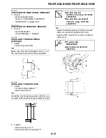
1. Measure:
• Brake pad wear limit “a”
Out of specification
→
Replace the brake
pads as a set.
2. Install:
• Brake pads
• Brake pad spring
TIP
Always install new brake pads and a new
brake pad spring as a set.
▼▼▼▼▼▼▼▼▼▼▼▼▼▼▼▼▼▼▼▼▼▼▼▼▼▼▼▼▼▼
a. Connect a clear plastic hose “1” tightly to
the bleed screw “2”. Put the other end of
the hose into an open container.
b. Loosen the bleed screw and push the
brake caliper pistons into the brake caliper
with your finger.
c. Tighten the bleed screw.
d. Install new brake pads and a new brake
pad spring.
▲▲▲▲▲▲▲▲▲▲▲▲▲▲▲▲▲▲▲▲▲▲▲▲▲▲▲▲▲▲
3. Lubricate:
• Brake caliper guide bar
ECA14150
• Do not allow grease to contact the brake
pads.
• Remove any excess grease.
4. Install:
• Brake pad retaining bolt
• Bolt
• Brake caliper
• Brake caliper bolts
5. Check:
• Brake fluid level
Below the minimum level mark “a”
→
Add
the recommended brake fluid to the
proper level.
Refer to “CHECKING THE BRAKE
FLUID LEVEL” on page 3-17.
6. Check:
• Brake lever operation
Soft or spongy feeling
→
Bleed the brake
system.
Refer to “BLEEDING THE HYDRAULIC
BRAKE SYSTEM” on page 3-20.
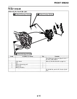
EAS22300
REMOVING THE FRONT BRAKE CALIPERS
The following procedure applies to both of the
brake calipers.
Brake pad lining thickness
(inner)
4.4 mm (0.17 in)
Limit
1.5 mm (0.06 in)
Brake pad lining thickness
(outer)
4.4 mm (0.17 in)
Limit
1.5 mm (0.06 in)
Bleed screw
5 Nm (0.5 m·kg, 3.7 ft·lb)
Recommended lubricant
Silicone grease
Brake pad retaining bolt
17 Nm (1.7 m·kg, 13 ft·lb)
Bolt
2.5 Nm (0.25 m·kg, 1.8 ft·lb)
Brake caliper bolt
28 Nm (2.8 m·kg, 21 ft·lb)
Summary of Contents for 2009 YFM25RY
Page 1: ...SERVICE MANUAL YFM25RY YFM25RSEY YFM25RSE2Y 4D3 28197 11 LIT 11616 22 09 2009 ...
Page 8: ......
Page 39: ...LUBRICATION POINTS AND LUBRICANT TYPES 2 20 ...
Page 42: ...LUBRICATION SYSTEM CHART AND DIAGRAMS 2 23 EAS20410 LUBRICATION DIAGRAMS ...
Page 44: ...LUBRICATION SYSTEM CHART AND DIAGRAMS 2 25 ...
Page 46: ...LUBRICATION SYSTEM CHART AND DIAGRAMS 2 27 ...
Page 47: ...LUBRICATION SYSTEM CHART AND DIAGRAMS 2 28 1 Oil cooler 2 Oil hose 1 3 Oil hose 2 ...
Page 48: ...CABLE ROUTING 2 29 EAS20430 CABLE ROUTING ...
Page 50: ...CABLE ROUTING 2 31 ...
Page 52: ...CABLE ROUTING 2 33 ...
Page 54: ...CABLE ROUTING 2 35 ...
Page 56: ...CABLE ROUTING 2 37 ...
Page 58: ...CABLE ROUTING 2 39 ...
Page 60: ...CABLE ROUTING 2 41 ...
Page 62: ...CABLE ROUTING 2 43 ...
Page 65: ......
Page 143: ...HANDLEBAR 4 42 Throttle cable free play 2 0 4 0 mm 0 08 0 16 in ...
Page 162: ...CHAIN DRIVE 4 61 ...
Page 165: ......
Page 240: ...CARBURETOR 6 9 ...
Page 242: ...IGNITION SYSTEM 7 1 EAS27090 IGNITION SYSTEM EAS27100 CIRCUIT DIAGRAM ...
Page 246: ...ELECTRIC STARTING SYSTEM 7 5 EAS27160 ELECTRIC STARTING SYSTEM EAS27170 CIRCUIT DIAGRAM ...
Page 252: ...CHARGING SYSTEM 7 11 EAS27200 CHARGING SYSTEM EAS27210 CIRCUIT DIAGRAM ...
Page 255: ...CHARGING SYSTEM 7 14 ...
Page 256: ...LIGHTING SYSTEM 7 15 EAS27240 LIGHTING SYSTEM EAS27250 CIRCUIT DIAGRAM ...
Page 260: ...SIGNALING SYSTEM 7 19 EAS27270 SIGNALING SYSTEM EAS27280 CIRCUIT DIAGRAM ...
Page 264: ...CARBURETOR HEATING SYSTEM 7 23 EAS27490 CARBURETOR HEATING SYSTEM EAS27500 CIRCUIT DIAGRAM ...
Page 267: ...CARBURETOR HEATING SYSTEM 7 26 ...
Page 268: ...ELECTRICAL COMPONENTS 7 27 EAS27972 ELECTRICAL COMPONENTS ...
Page 270: ...ELECTRICAL COMPONENTS 7 29 EAS27980 CHECKING THE SWITCHES ...
Page 284: ...ELECTRICAL COMPONENTS 7 43 ...
Page 291: ......
Page 292: ...YAMAHA MOTOR CO LTD 2500 SHINGAI IWATA SHIZUOKA JAPAN ...
Page 293: ...WIRING DIAGRAM YFM25RY YFM25RSEY YFM25RSE2Y ...